Demo 4
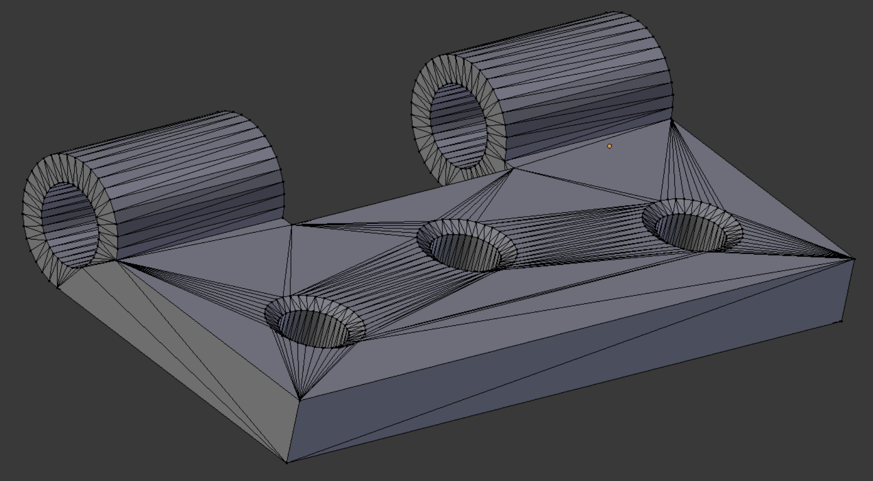
This object is a hinge. The .stl file of this object is obtained from the Elmer GUI samples folder (see References), and imported into Blender.
This demo has more step-by-step comments than the others in this document.
This object is a hinge. The .stl file of this object is obtained from the Elmer GUI samples folder (see References), and imported into Blender.
This demo has more step-by-step comments than the others in this document.
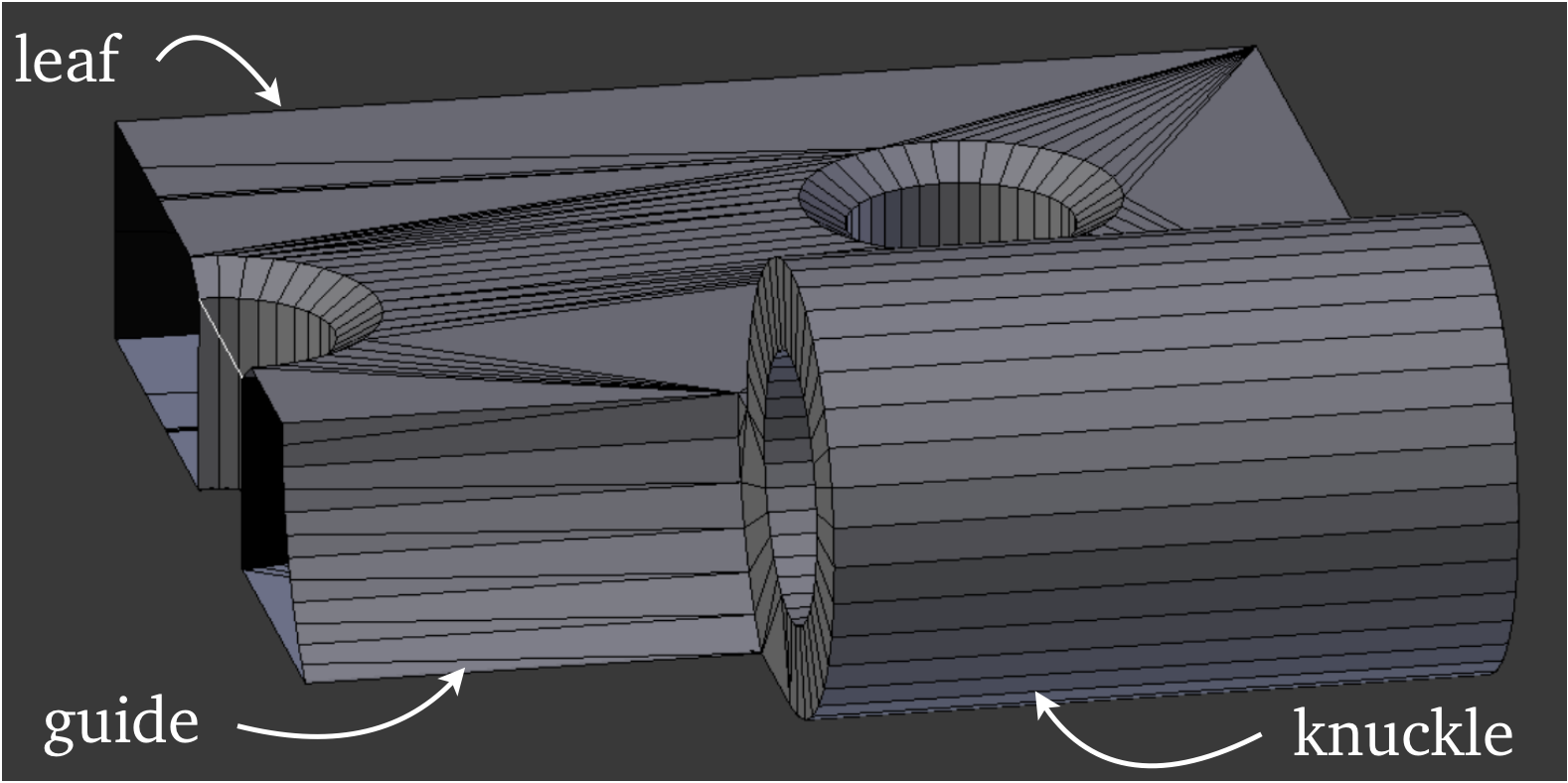
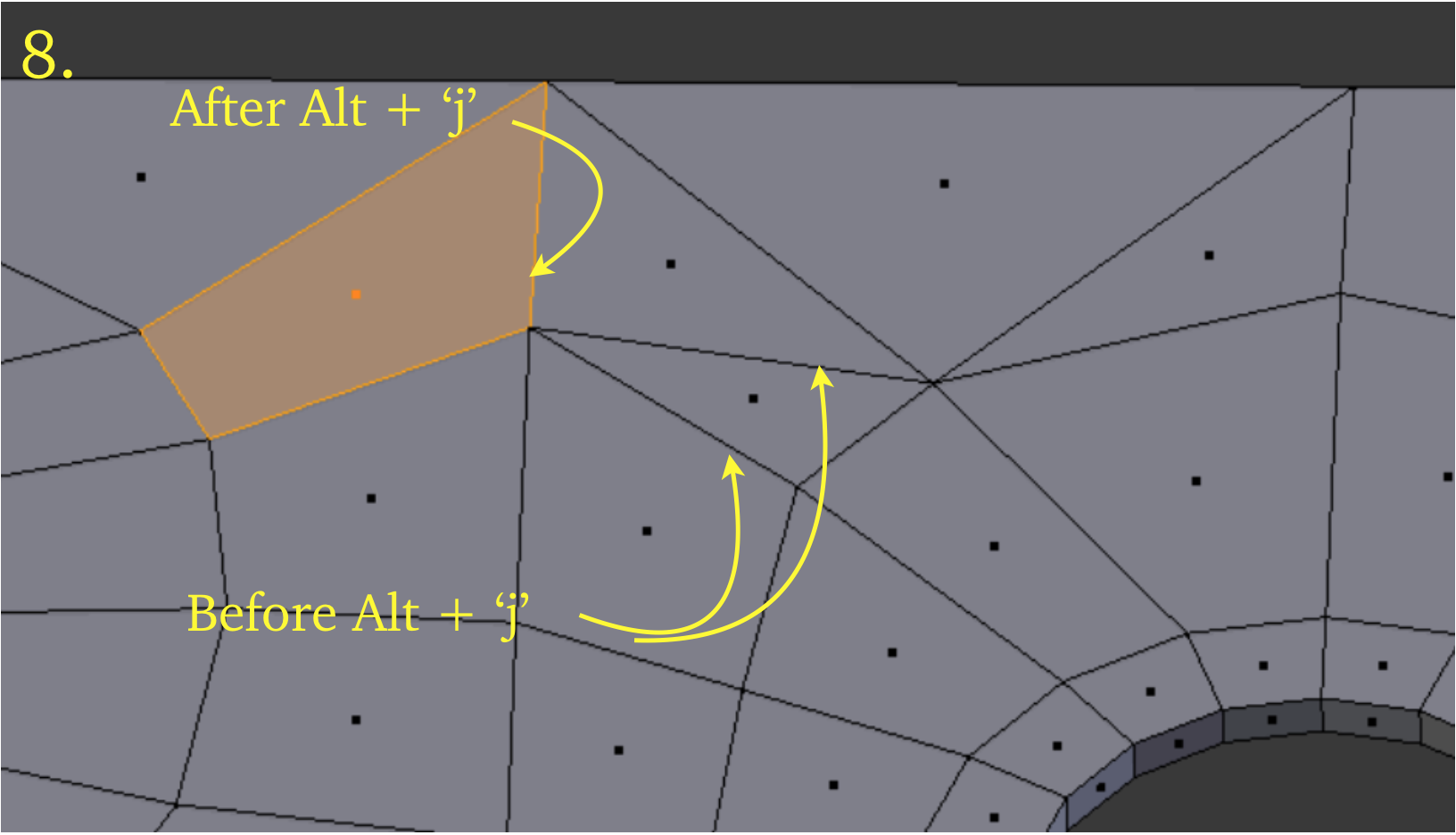
We first select a vertical edge, press Shift + ‘d’ (Duplicate), then ‘p’ (Separate) the edge into a separate object. We use the Knife Project command by selecting a random edge in Edit mode which will be used for cutting and modifying it so that from a chosen viewpoint it cuts as we wish. Then in Object mode we select first the cutter then the mesh. Then back in Edit mode we cut the model exactly in half vertically. We apply the Alt + ‘j’ command to turn some of the triangles into quads.
We cut horizontally at a convenient place to isolate the leaf section from the knuckle section, using a randomly selected and modified horizontal edge as cutter. The knuckle section we place on a separate layer temporarily.
We select the surface edges and use the Mesh → Clean Up → Limited Dissolve command at default strength to eliminate the selected edges, leaving only a couple left after the command has finished.
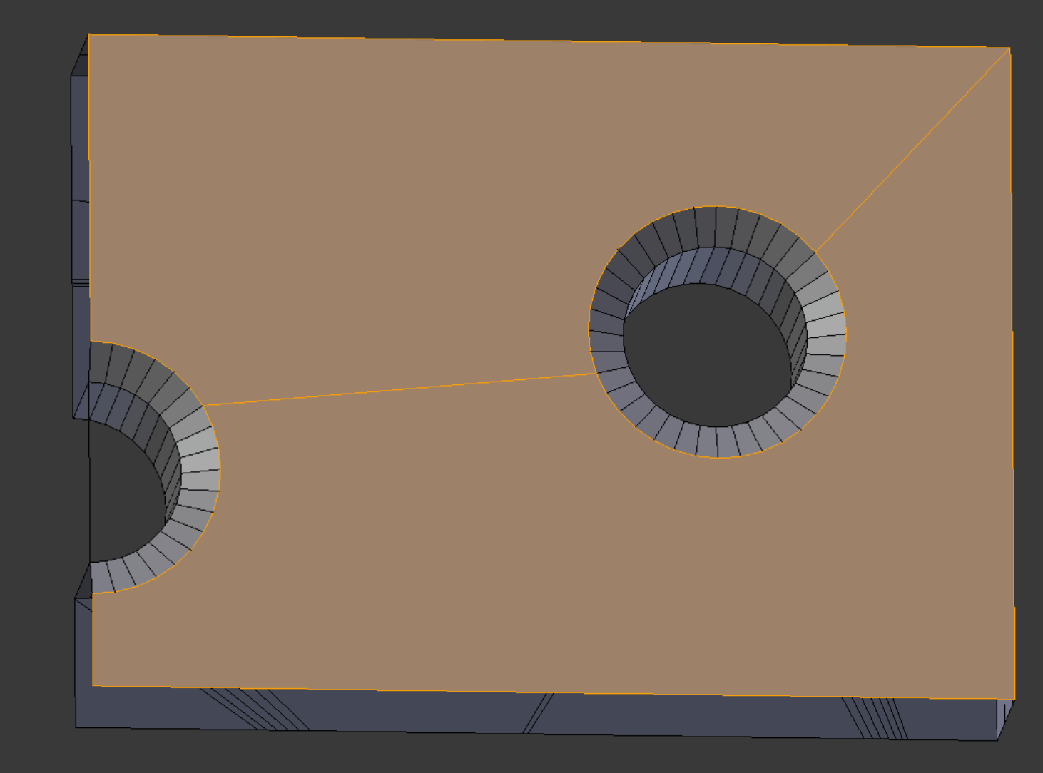
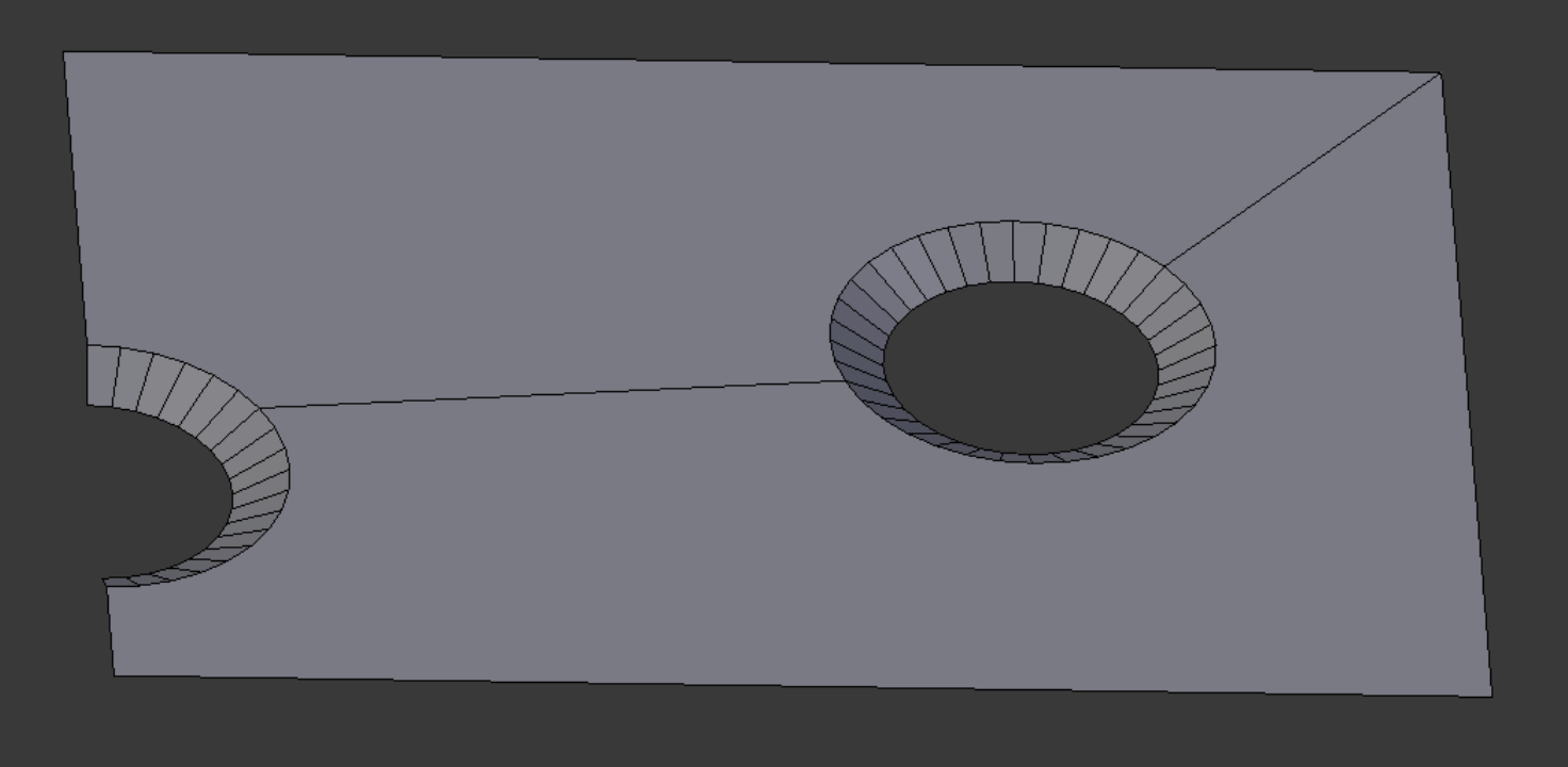
We note down the z-axis thickness of the leaf (5.0) and then delete all but the top layer of faces (plus hole bevels).
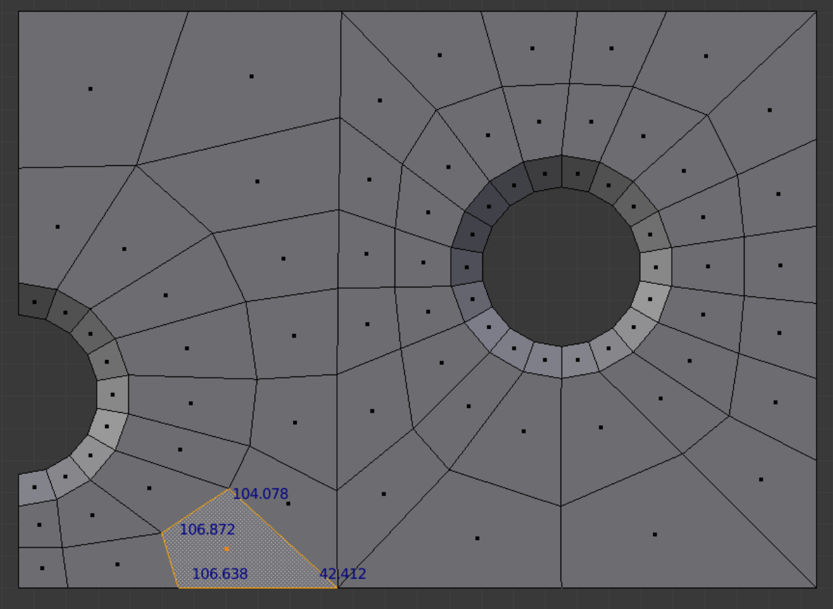
We reduce the hole divisions from 36 to 18 by merging points. We then use the Knife command by pressing ‘k’. We divide up the surface into faces with reasonably sized angles. We review the angle sizes using the Angle checkbox under the Mesh Display section of the ‘n’ properties panel. For mesh quality purposes we generally try to keep all angles less than 130 degrees and greater than 40 degrees, with no two angles in a face differing by more than 75 degrees.
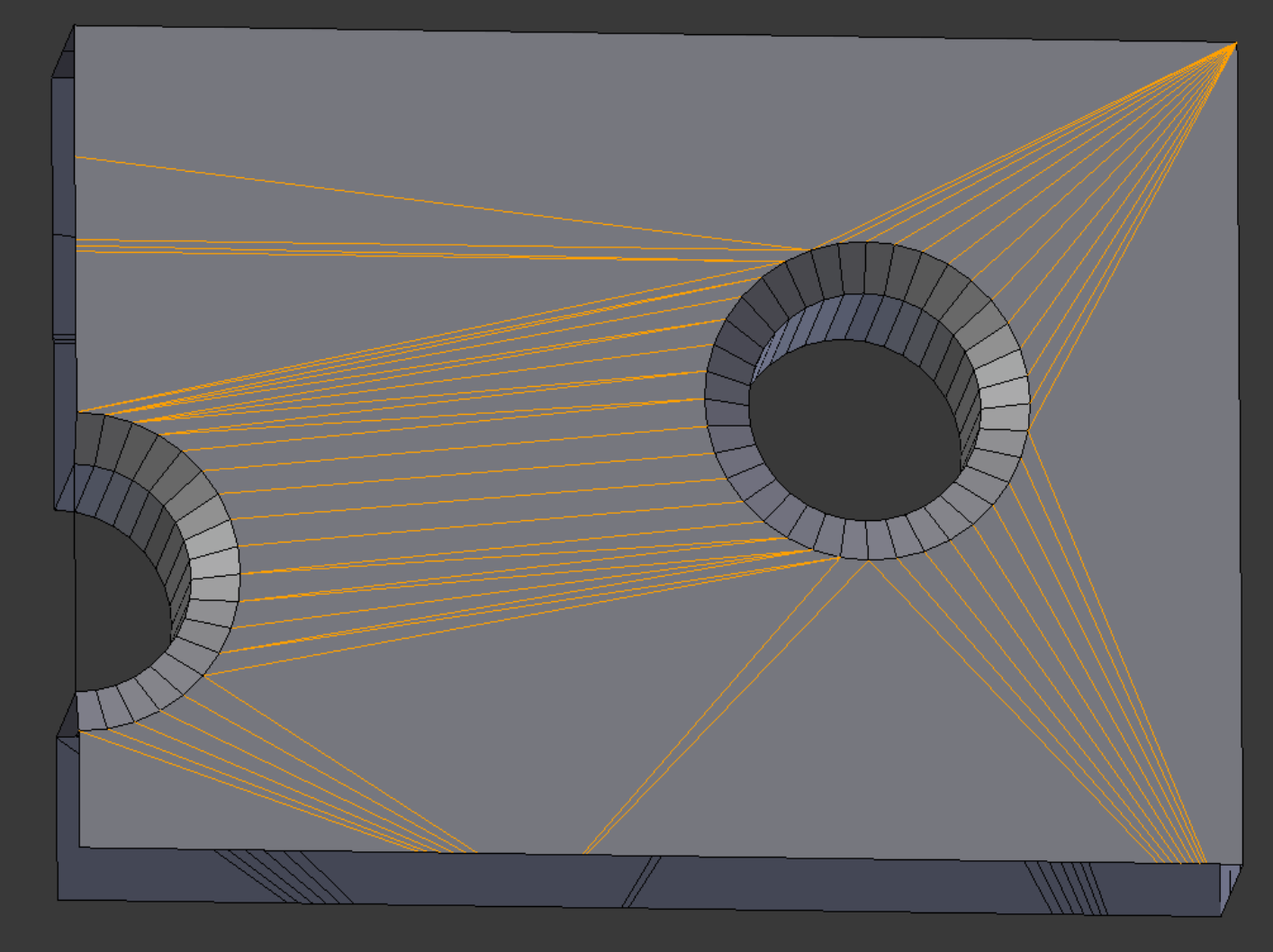
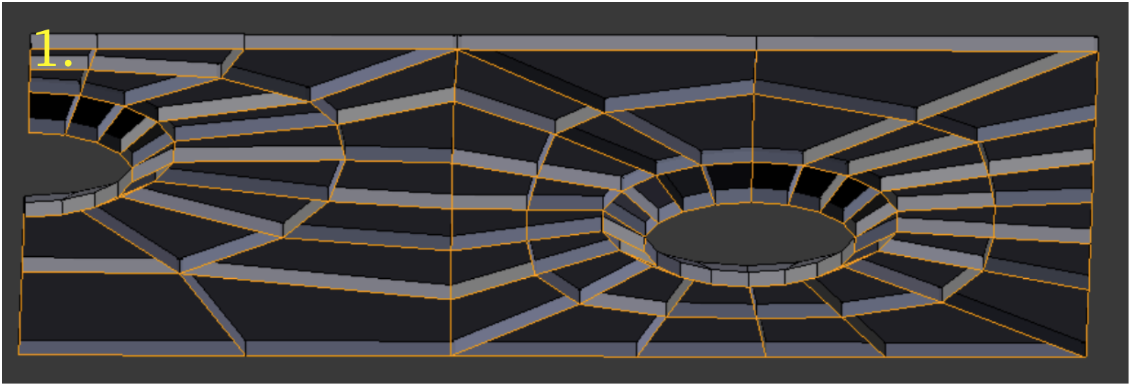
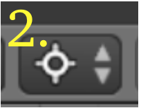
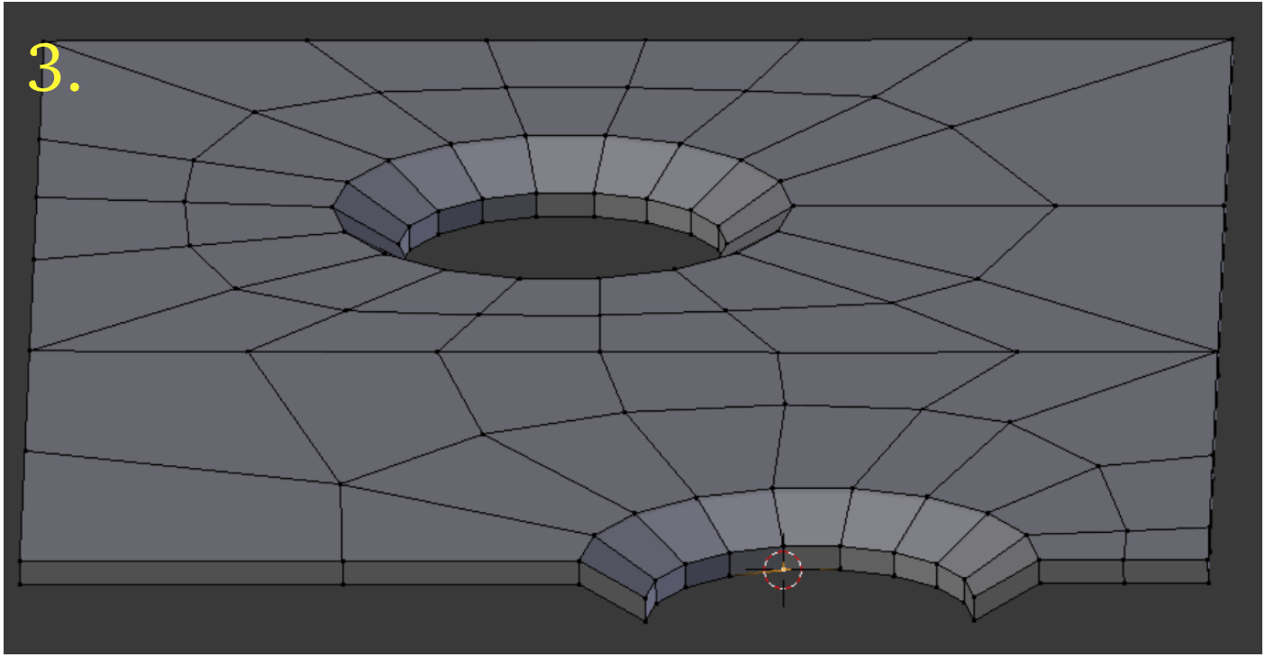
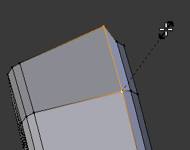
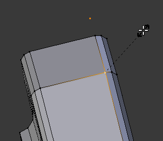
Now we do our first extrusion. We select all the faces with the boundary selection command. We then change the mode to edge select, the selected edges showing selection glow. Then we press Alt + ‘e’, followed by selection of ‘Edges Only.’ Then we enter ‘-.37983 z’ and press Return. The edges extrude downward by .37983 units, as shown in picture 1, an underside view. Next we select the 3D cursor as pivot point, picture 2. Now we switch to point select mode and select one of the lower inside hole points, as in picture 3, and then we press Shift + ‘s’, followed by ‘u’ to send the 3D cursor to the selected point.
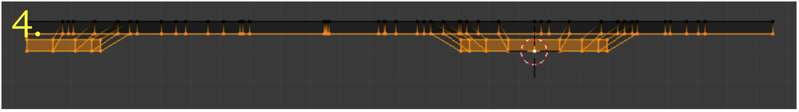
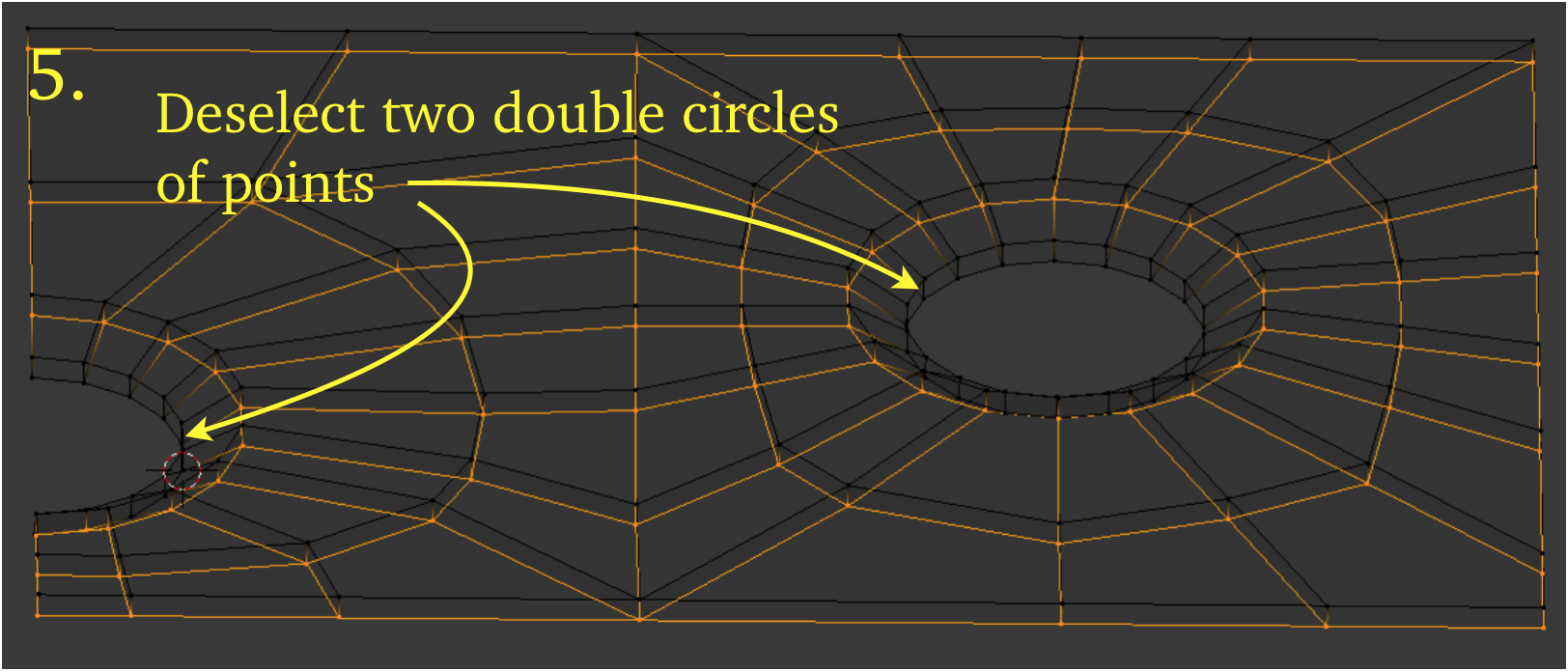
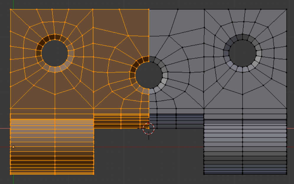
We then take a front view by pressing ‘1’. We go into wire frame mode by pressing ‘z’. We boundary select all the points below the top surface, as in picture 4. We now use the circle select command, ‘c’, along with the Shift key, to deselect the innermost points in the holes, as in picture 5. Next we press ‘s’ (Scale) + ‘z’ + ‘0’, and then press Return.
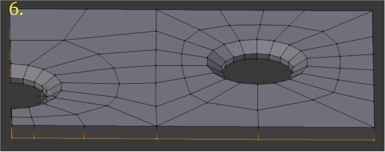
All the points except those which were not selected jump to the 3D cursor z-position, which is .37983 units below the top surface, as seen in picture 6.
Our next task is to cover the newly extruded edges with faces. We take a front view, ‘1’, and go into wire frame mode, ‘z’, and into edge select mode.
We have extruded the first level of the leaf section. To create the other five levels is similar and simpler. We put the mesh into front view with ‘1’, go into wire frame mode with ‘z’, go into face select mode, and carefully select the bottom layer of faces. Then we fall back to edge select mode and repeat the routine: 1. press Alt + ‘e’, 2. selection of option ‘Edges Only’, 3. enter ‘-.next-z + z’ and 4. press Return, where ‘-.next-z’ represents the next value in the sequence: -.95431, -.90227, -.82596, -.72743, and -.60934.
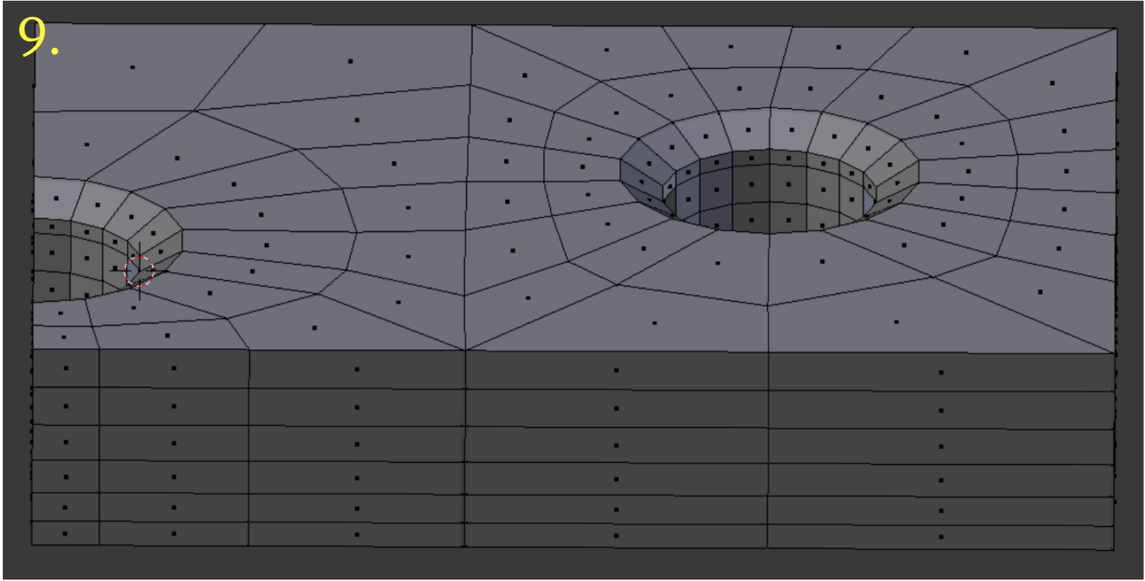
This results in something like picture 9, which is a skirt of faces with only the first two horizontal levels populated with faces. The next task then is to put in the horizontal layers. We do this with a slight variation on the routine just used.
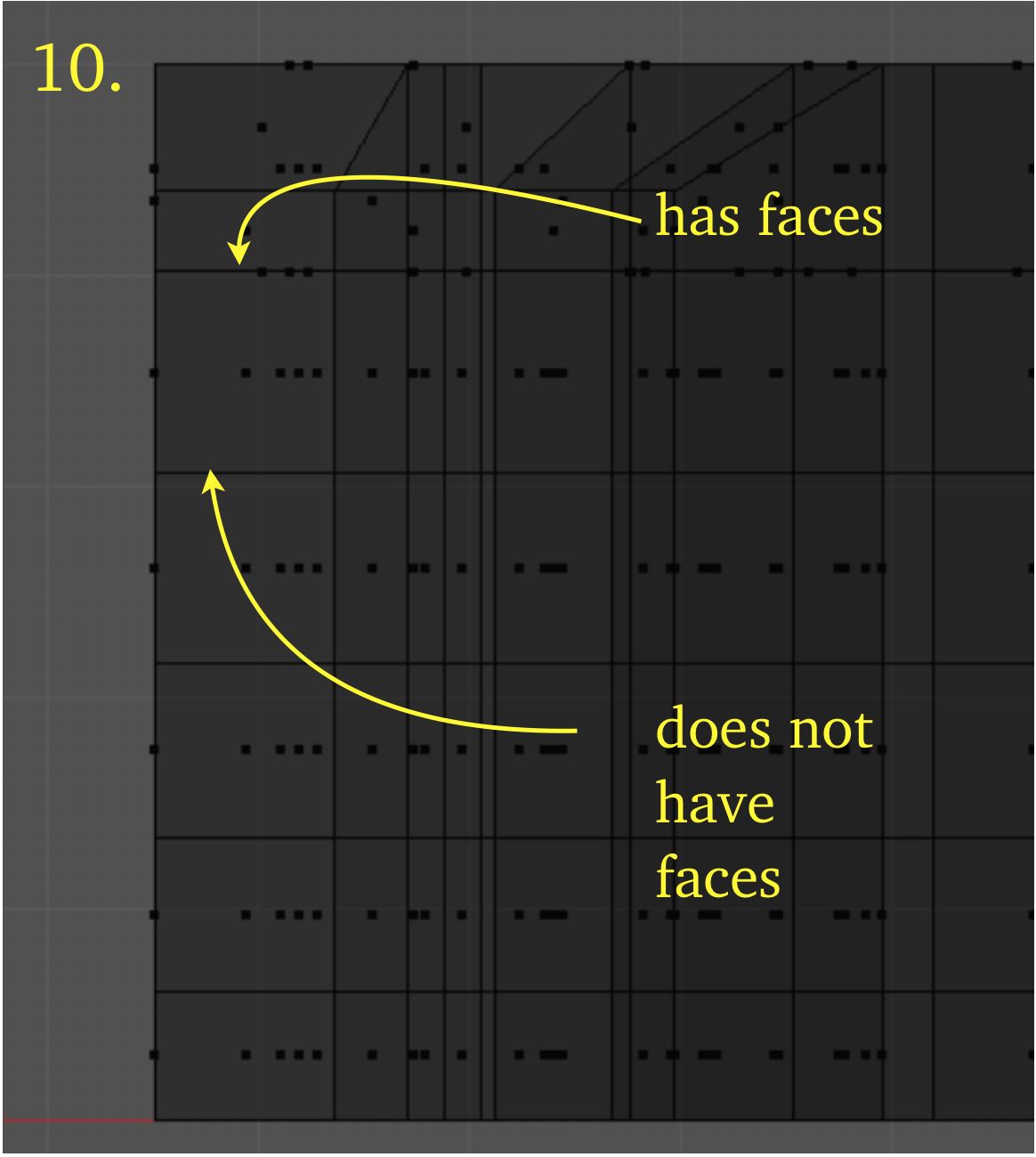
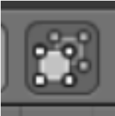
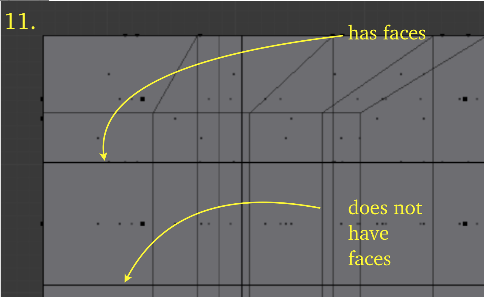
We select the bottom layer of faces, as in picture 10, (or picture 11, using ‘Limit Selection’ button) with the face dots confirming which layer has the faces. Then we use the command Shift + ‘d’ (Duplicate) to duplicate the face layer. We immediately enter the distance of movement and the axis, and press Return. For example, the first is ‘-.95431 z’. If we make a numerical mistake, we will see too many layers of horizontal edges when we come out of wire frame mode. When we have finished, we select everything and Remove Doubles, finding that 535 doubles are removed. The degree of Verdict quality does not appear to be a potential issue with the leaf section, so we will not bother with doing that check.
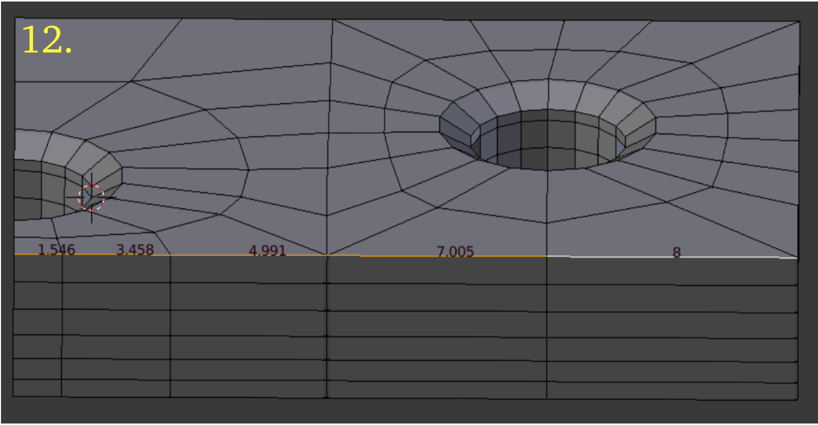
Before moving on to the construction of the guide, there are five edge lengths we need to capture, as shown in picture 12. They turn out to be: 1.546, 3.458, 4.991, 7.005, and 8, as revealed by Edge info: Length, under Mesh Display in the ‘n’ properties panel.
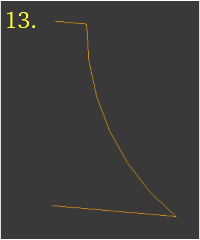
We start with the edge outline of the guide that was cut with the dividing knife, seen in picture 13. We first make an n-gon, using ‘f’ (Face), then use the knife tool to cut it into horizontal faces.
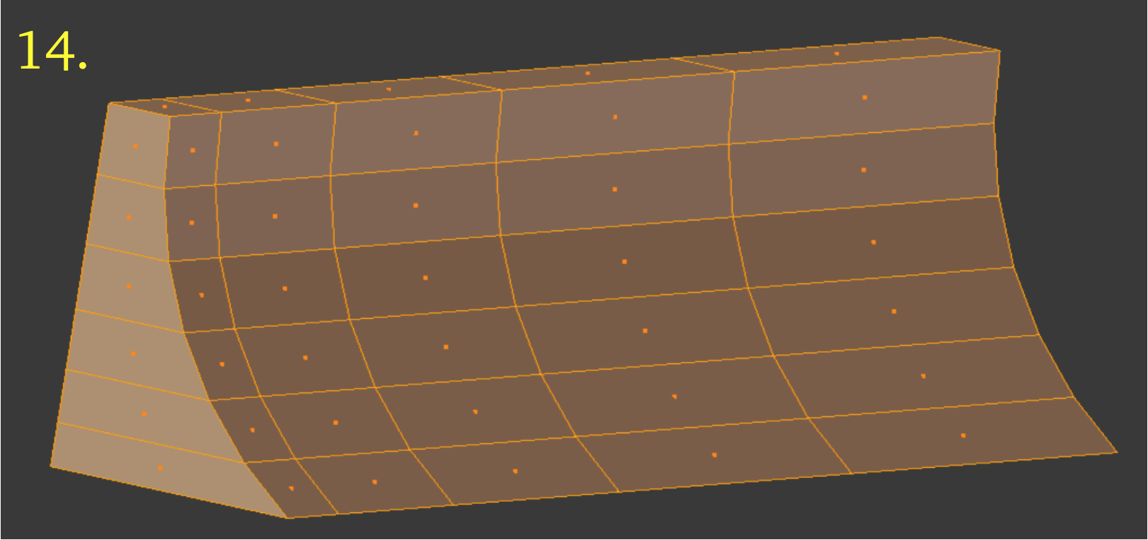
These we extrude horizontally along the x-axis using the edge lengths found above, as shown in picture 14, so that they will match the edges of the leaf. We add vertical layers of faces exactly as we added the horizontal layers before, by duplication. When we remove doubles, Blender reports the removal of 70 doubles.
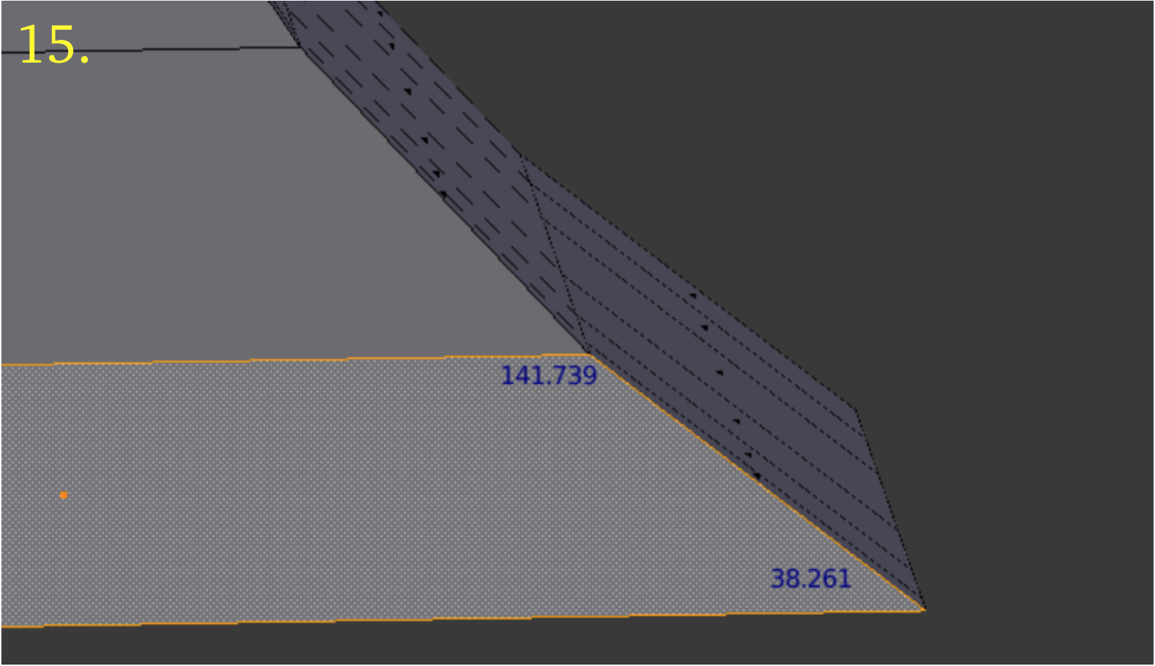
There is one serious concern about the guide, which is the extreme angles on its lowest faces, as seen in picture 15. Two angles violate all three of the rules we mentioned before about angle quality. So we have to take time to check out the quality of the guide.
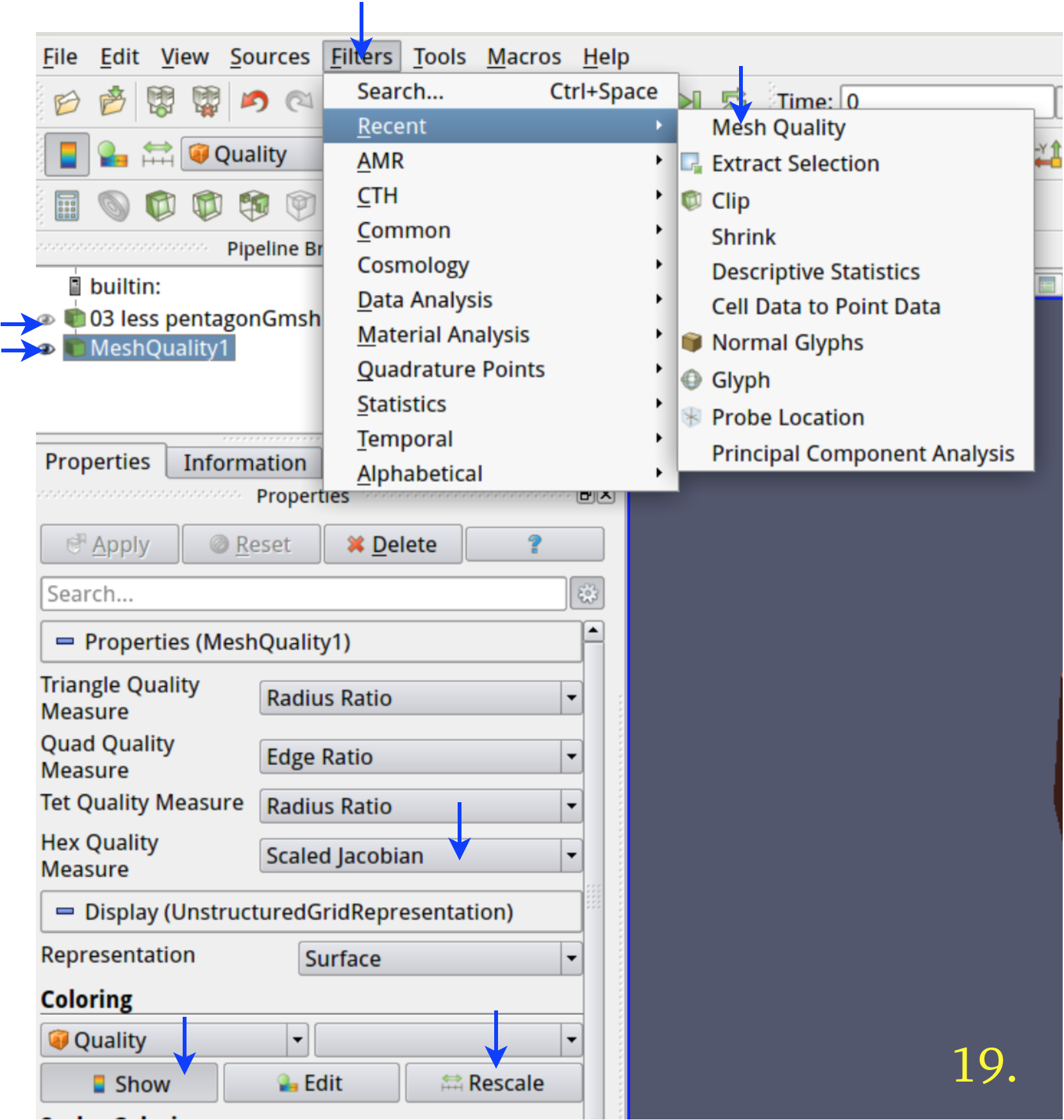
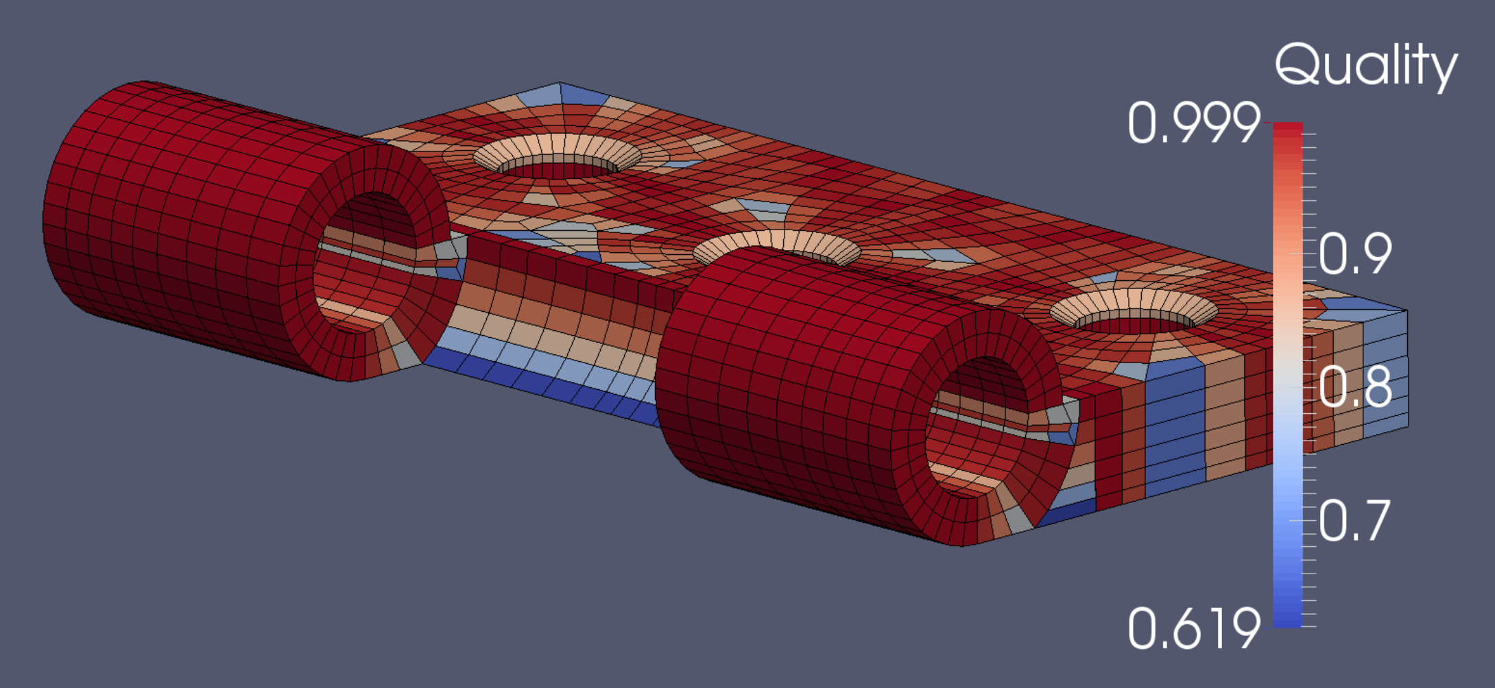
We open the resulting .vtk in Paraview, the GUI of which is shown in picture 19, with arrows at labels of interest. We apply the Mesh Quality filter, dial the Hex Quality Measure spinner button down to Scaled Jacobian, click the Show and Rescale buttons under Coloring, and find the circumstance shown in picture 20.
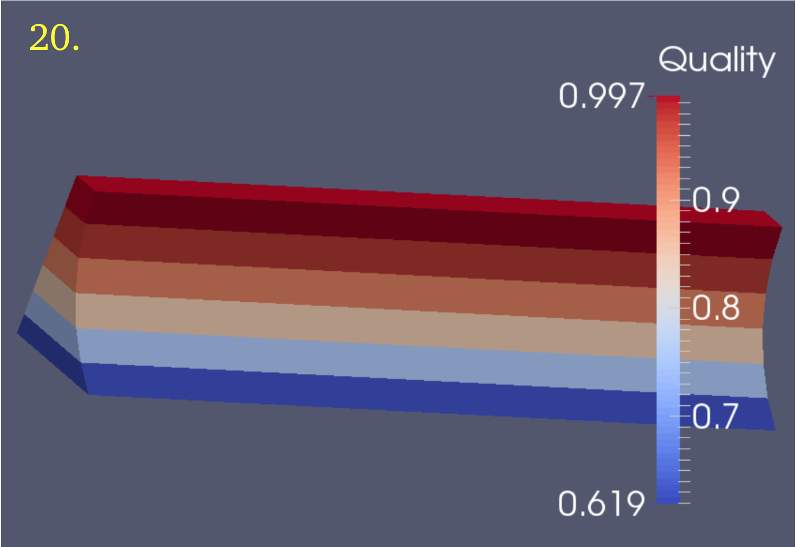
According to the Verdict quality assessment system embodied in the Paraview Mesh Quality filter, elements with a Scaled Jacobian score between 0.5 and 1.0 are acceptable.The guide has surprisingly good quality for its poor angles, and shows a minimum quality level of 0.619. We speculate that the nice flat sides compensate for the poor angles.
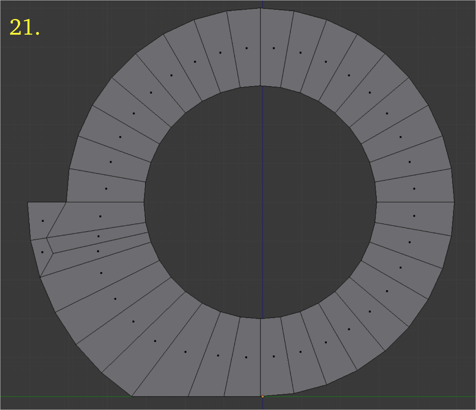
It is time to move on to the knuckle. The knuckle end plate which is adjacent to the guide we now duplicate and put on a new layer. We eliminate triangles by hand, making angles as favorable as possible. As picture 21 shows, the outline is in no way extreme and the angles do not give difficulty.
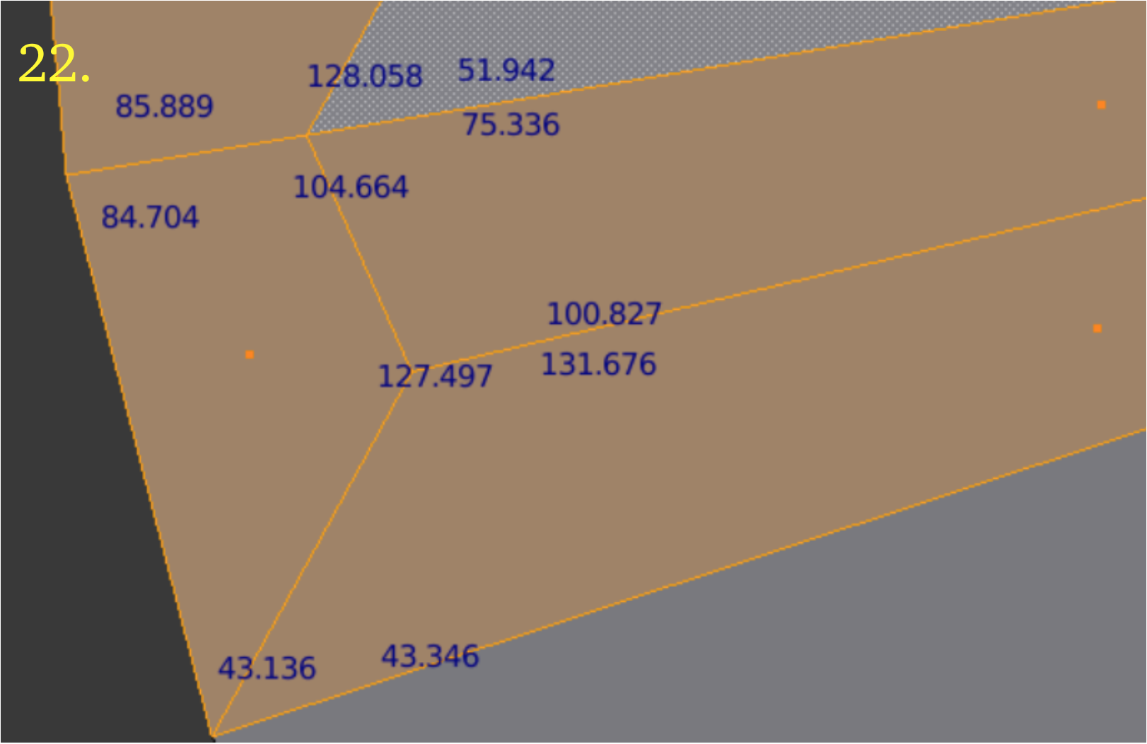
Picture 22 shows the worst angles. The x-value of the end we are working on is 34.5, which means there are two horizontal extrusions to be accomplished. We do these just as we did for the guide.
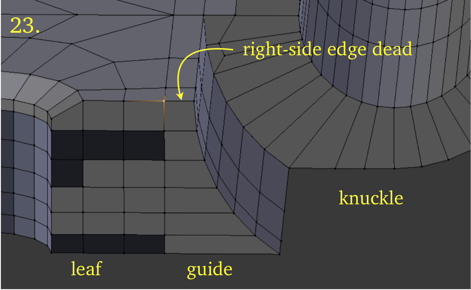
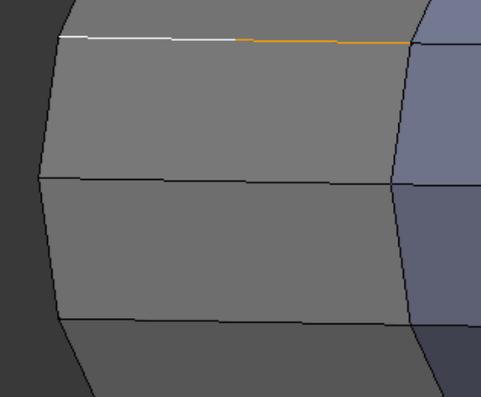
It remains to assemble the hinge. We put the three subassemblies on the same layer and join them. After joining, it is necessary to check the points involved to make sure they are sound. Picture 23 shows an unsound one immediately. We can see that for this selected point, the selected point ‘edge glow’ does not extend from the leaf side to the guide side, as it should.
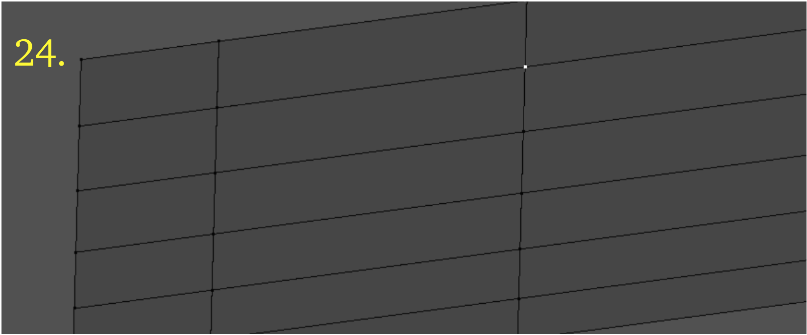
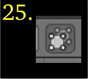
We take a top view, ‘7’, and in point select mode we boundary select and hide all points which are not on the join boundary between leaf and guide. We go into wire frame mode and take any convenient perspective. Then we select each point, clicking on it at least twice. The first time it may glow in all directions, but on the second click it may go dead, as shown for the point in picture 24. Indeed, it would be surprising if they were not all half dead. For each one so found, we ‘c’, circle select around it and merge the points. Note that is only works in wire frame mode, or in the mode governed by the button with Tooltip, “Limit selection to visible”, shown in picture 25. At the boundary plane between guide and knuckle, we repeat the process of verifying soundness of points, though this boundary does have a curve.
Our next task is to check the quality of the assembly, using the same steps as when we checked the guide quality. We find that Verdict calculations give the subassembly a score of 0.619, the same as the guide achieved earlier. With this value determined, we can go on to the mirroring.
The division cut runs along the y-axis, but we want to mirror around global x. Before mirroring, we select a base point on the mesh and send the 3D cursor there to anchor the action. Then we Shift + ‘d’ (Duplicate) the mesh and perform the mirroring on the still-selected duplicate. After the mirroring, we select everything and Remove doubles. Blender reports the removal of 147 doubles.
We cut horizontally at a convenient place to isolate the leaf section from the knuckle section, using a randomly selected and modified horizontal edge as cutter. The knuckle section we place on a separate layer temporarily.
We select the surface edges and use the Mesh → Clean Up → Limited Dissolve command at default strength to eliminate the selected edges, leaving only a couple left after the command has finished.
We note down the z-axis thickness of the leaf (5.0) and then delete all but the top layer of faces (plus hole bevels).
We reduce the hole divisions from 36 to 18 by merging points. We then use the Knife command by pressing ‘k’. We divide up the surface into faces with reasonably sized angles. We review the angle sizes using the Angle checkbox under the Mesh Display section of the ‘n’ properties panel. For mesh quality purposes we generally try to keep all angles less than 130 degrees and greater than 40 degrees, with no two angles in a face differing by more than 75 degrees.
Now we do our first extrusion. We select all the faces with the boundary selection command. We then change the mode to edge select, the selected edges showing selection glow. Then we press Alt + ‘e’, followed by selection of ‘Edges Only.’ Then we enter ‘-.37983 z’ and press Return. The edges extrude downward by .37983 units, as shown in picture 1, an underside view. Next we select the 3D cursor as pivot point, picture 2. Now we switch to point select mode and select one of the lower inside hole points, as in picture 3, and then we press Shift + ‘s’, followed by ‘u’ to send the 3D cursor to the selected point.
We then take a front view by pressing ‘1’. We go into wire frame mode by pressing ‘z’. We boundary select all the points below the top surface, as in picture 4. We now use the circle select command, ‘c’, along with the Shift key, to deselect the innermost points in the holes, as in picture 5. Next we press ‘s’ (Scale) + ‘z’ + ‘0’, and then press Return.
All the points except those which were not selected jump to the 3D cursor z-position, which is .37983 units below the top surface, as seen in picture 6.
Our next task is to cover the newly extruded edges with faces. We take a front view, ‘1’, and go into wire frame mode, ‘z’, and into edge select mode.
We have extruded the first level of the leaf section. To create the other five levels is similar and simpler. We put the mesh into front view with ‘1’, go into wire frame mode with ‘z’, go into face select mode, and carefully select the bottom layer of faces. Then we fall back to edge select mode and repeat the routine: 1. press Alt + ‘e’, 2. selection of option ‘Edges Only’, 3. enter ‘-.next-z + z’ and 4. press Return, where ‘-.next-z’ represents the next value in the sequence: -.95431, -.90227, -.82596, -.72743, and -.60934.
This results in something like picture 9, which is a skirt of faces with only the first two horizontal levels populated with faces. The next task then is to put in the horizontal layers. We do this with a slight variation on the routine just used.
We select the bottom layer of faces, as in picture 10, (or picture 11, using ‘Limit Selection’ button) with the face dots confirming which layer has the faces. Then we use the command Shift + ‘d’ (Duplicate) to duplicate the face layer. We immediately enter the distance of movement and the axis, and press Return. For example, the first is ‘-.95431 z’. If we make a numerical mistake, we will see too many layers of horizontal edges when we come out of wire frame mode. When we have finished, we select everything and Remove Doubles, finding that 535 doubles are removed. The degree of Verdict quality does not appear to be a potential issue with the leaf section, so we will not bother with doing that check.
Before moving on to the construction of the guide, there are five edge lengths we need to capture, as shown in picture 12. They turn out to be: 1.546, 3.458, 4.991, 7.005, and 8, as revealed by Edge info: Length, under Mesh Display in the ‘n’ properties panel.
We start with the edge outline of the guide that was cut with the dividing knife, seen in picture 13. We first make an n-gon, using ‘f’ (Face), then use the knife tool to cut it into horizontal faces.
These we extrude horizontally along the x-axis using the edge lengths found above, as shown in picture 14, so that they will match the edges of the leaf. We add vertical layers of faces exactly as we added the horizontal layers before, by duplication. When we remove doubles, Blender reports the removal of 70 doubles.
There is one serious concern about the guide, which is the extreme angles on its lowest faces, as seen in picture 15. Two angles violate all three of the rules we mentioned before about angle quality. So we have to take time to check out the quality of the guide.
We open the resulting .vtk in Paraview, the GUI of which is shown in picture 19, with arrows at labels of interest. We apply the Mesh Quality filter, dial the Hex Quality Measure spinner button down to Scaled Jacobian, click the Show and Rescale buttons under Coloring, and find the circumstance shown in picture 20.
According to the Verdict quality assessment system embodied in the Paraview Mesh Quality filter, elements with a Scaled Jacobian score between 0.5 and 1.0 are acceptable.The guide has surprisingly good quality for its poor angles, and shows a minimum quality level of 0.619. We speculate that the nice flat sides compensate for the poor angles.
It is time to move on to the knuckle. The knuckle end plate which is adjacent to the guide we now duplicate and put on a new layer. We eliminate triangles by hand, making angles as favorable as possible. As picture 21 shows, the outline is in no way extreme and the angles do not give difficulty.
Picture 22 shows the worst angles. The x-value of the end we are working on is 34.5, which means there are two horizontal extrusions to be accomplished. We do these just as we did for the guide.
It remains to assemble the hinge. We put the three subassemblies on the same layer and join them. After joining, it is necessary to check the points involved to make sure they are sound. Picture 23 shows an unsound one immediately. We can see that for this selected point, the selected point ‘edge glow’ does not extend from the leaf side to the guide side, as it should.
We take a top view, ‘7’, and in point select mode we boundary select and hide all points which are not on the join boundary between leaf and guide. We go into wire frame mode and take any convenient perspective. Then we select each point, clicking on it at least twice. The first time it may glow in all directions, but on the second click it may go dead, as shown for the point in picture 24. Indeed, it would be surprising if they were not all half dead. For each one so found, we ‘c’, circle select around it and merge the points. Note that is only works in wire frame mode, or in the mode governed by the button with Tooltip, “Limit selection to visible”, shown in picture 25. At the boundary plane between guide and knuckle, we repeat the process of verifying soundness of points, though this boundary does have a curve.
Our next task is to check the quality of the assembly, using the same steps as when we checked the guide quality. We find that Verdict calculations give the subassembly a score of 0.619, the same as the guide achieved earlier. With this value determined, we can go on to the mirroring.
The division cut runs along the y-axis, but we want to mirror around global x. Before mirroring, we select a base point on the mesh and send the 3D cursor there to anchor the action. Then we Shift + ‘d’ (Duplicate) the mesh and perform the mirroring on the still-selected duplicate. After the mirroring, we select everything and Remove doubles. Blender reports the removal of 147 doubles.

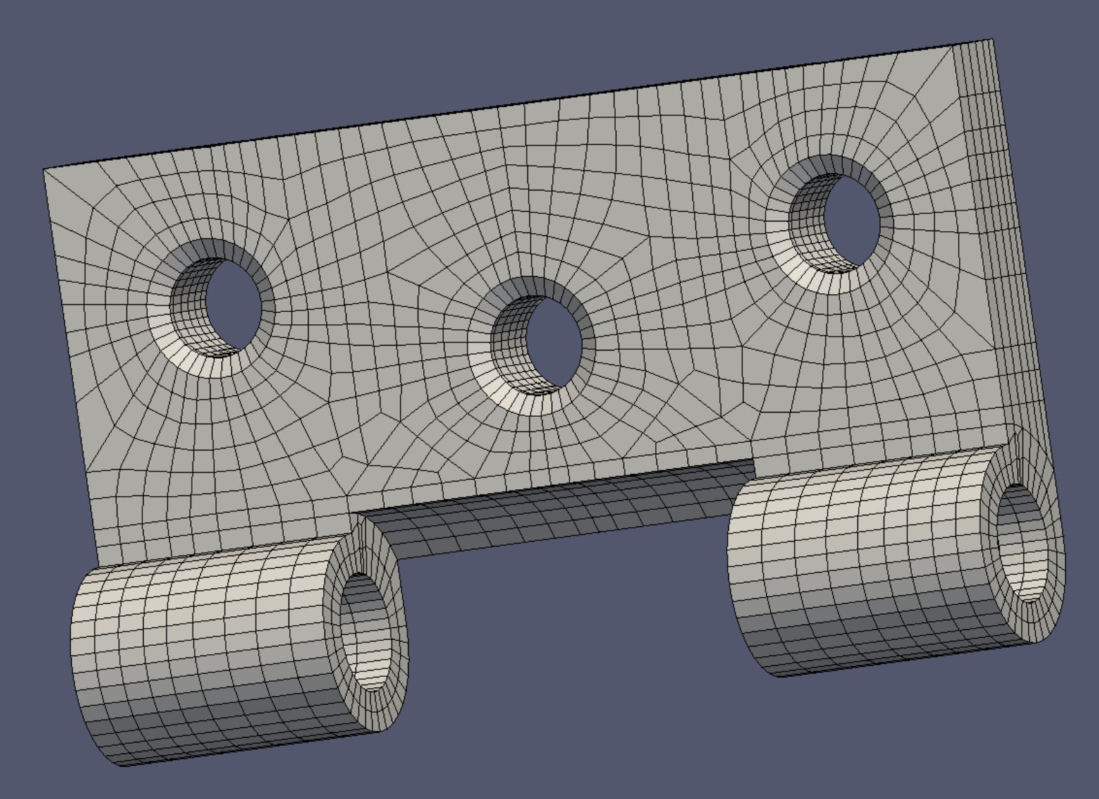
Using the process described so far in this demo, we create a mesh with a slightly different face pattern. The 18,676 faces of this final mesh require 65 seconds for Blenbridge to convert to .vtk. The final totals are 5556 elements and 7888 nodes.
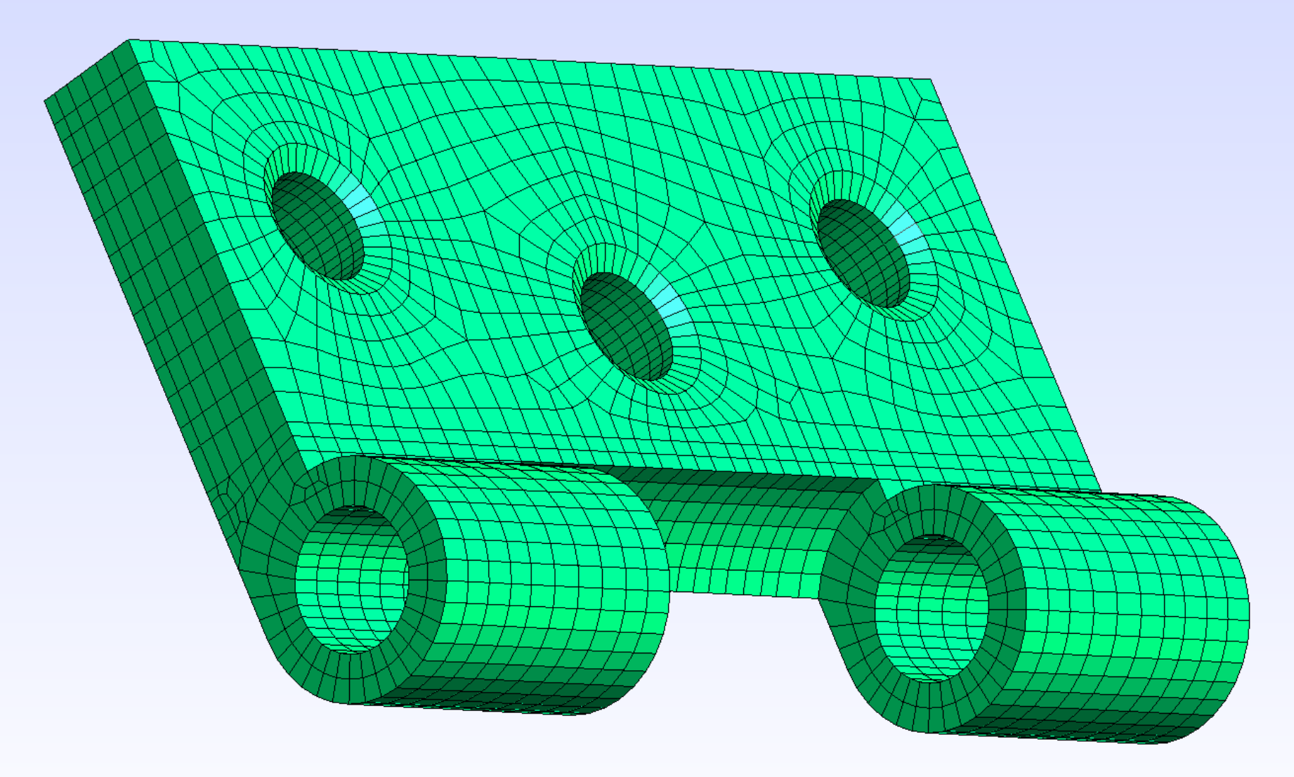
Shown above is the Mesh Quality filter view in Paraview, which evaluates the mesh. With a minimum of 0.619 for all the elements, the mesh scores within the Verdict standard.
Shown above is the Mesh Quality filter view in Paraview, which evaluates the mesh. With a minimum of 0.619 for all the elements, the mesh scores within the Verdict standard.
Here we offer a few edge tricks.
1. A fundamental geometry-creation step in Blender is splitting an edge. The keyboard steps for the selected edge are Ctrl+ ‘e’, followed by ’s’. Both halves remain selected, and if in this state the command is repeated, both edges will be split, allowing quick division into 2, 4, 8, or 16 pieces, as required.
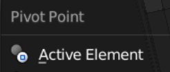
2. Sliding a selected point along an edge is Shift + ‘v’. But to extend the end point of an edge, make sure that the pivot point is ‘Active Element’. Then first select the point to be stretched, then its base point, then ‘s’ (Scale).
3. Using the same pivot point as 2, but creating a new edge with the same direction as the original. After selecting the first point, press Shift + ‘d’ (Duplicate). Then press Escape to keep the new point from wandering. Then select the base point, press ‘s’ (Scale), and position the new point with its inherited directionality . Now the point can be connected with the last end point with the ‘f’ (Face) command to create new geometry.
1. A fundamental geometry-creation step in Blender is splitting an edge. The keyboard steps for the selected edge are Ctrl+ ‘e’, followed by ’s’. Both halves remain selected, and if in this state the command is repeated, both edges will be split, allowing quick division into 2, 4, 8, or 16 pieces, as required.
2. Sliding a selected point along an edge is Shift + ‘v’. But to extend the end point of an edge, make sure that the pivot point is ‘Active Element’. Then first select the point to be stretched, then its base point, then ‘s’ (Scale).
3. Using the same pivot point as 2, but creating a new edge with the same direction as the original. After selecting the first point, press Shift + ‘d’ (Duplicate). Then press Escape to keep the new point from wandering. Then select the base point, press ‘s’ (Scale), and position the new point with its inherited directionality . Now the point can be connected with the last end point with the ‘f’ (Face) command to create new geometry.
If the mesh is saved in Gmsh as a .msh file, it can be loaded into Elmer. Elmer will not attempt to remesh it. Saved in Gmsh as a .inp file, it can be used in Calculix or Febio.
Although the Verdict test for Scaled Jacobian is a useful one, we get the sense that it may be a bit too lenient on the trait of element shape. For the mesh shown in the last picture, we therefore run a test on all 19 Verdict attributes covered by the Paraview mesh quality filter.
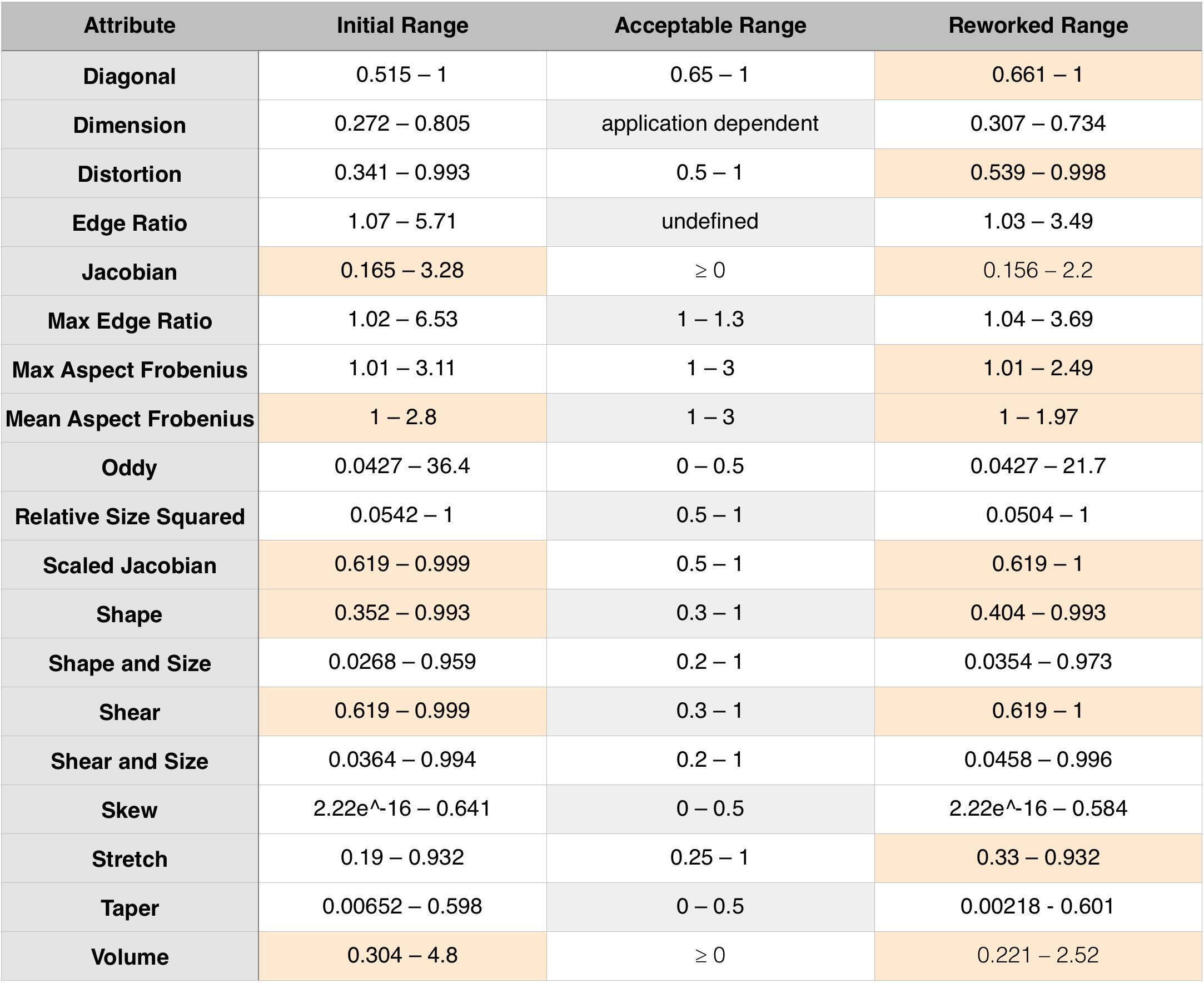
The table shows that the initial mesh has 6 of 17 categories satisfied, or a raw measure of 35 percent of the available categories. We will consider the categories of Diagonal and Distortion.
By requesting an additional Layout in Paraview, choosing a Spreadsheet Layout, and then using normal spreadsheet highlighting functions, the non-compliant elements can be captured with an Extract Selection filter and displayed.
The picture at right shows the 90 elements which do not initially meet the Verdict standards for Diagonal.
The picture at right shows the 90 elements which do not initially meet the Verdict standards for Diagonal.
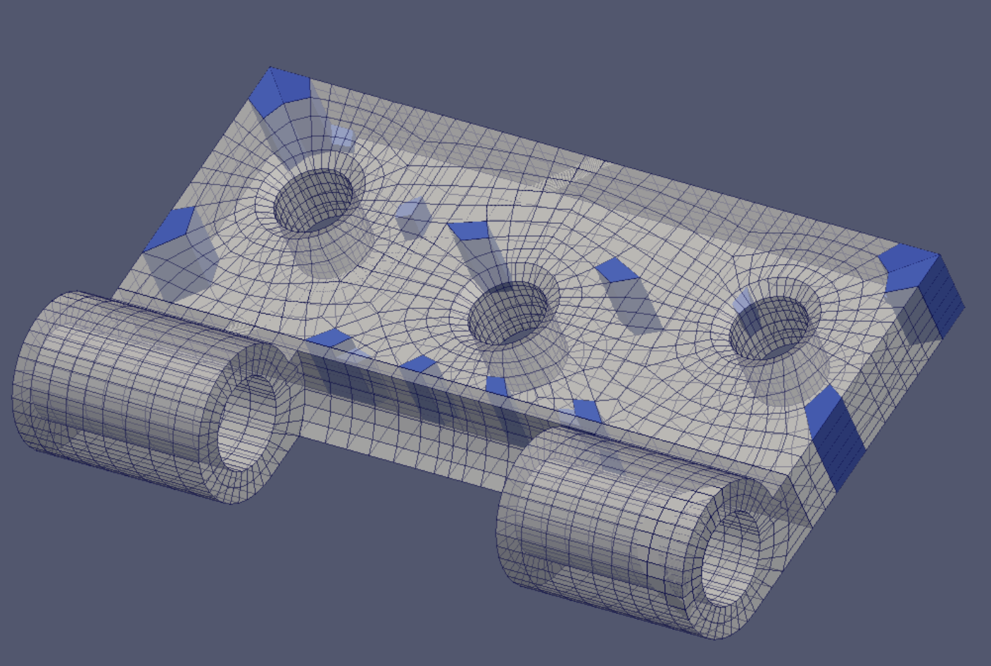
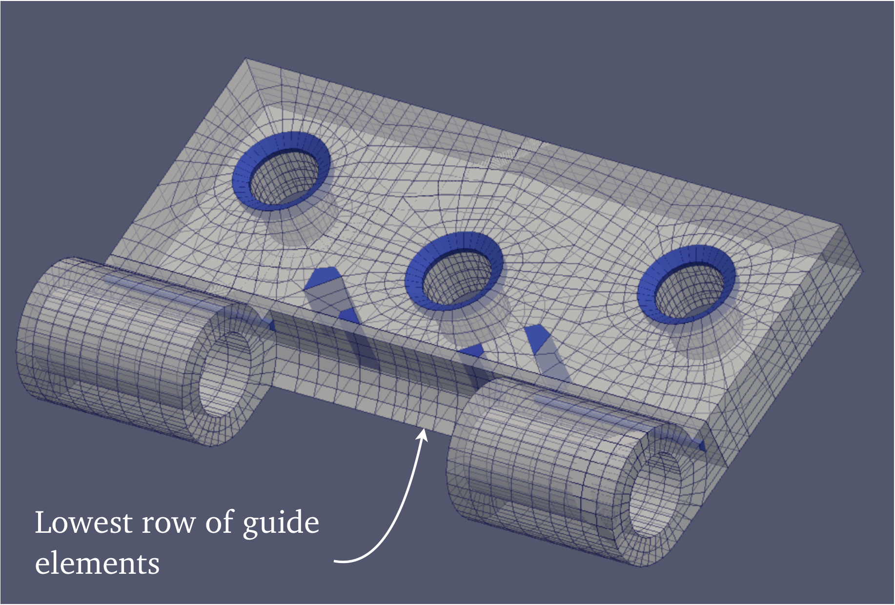
The picture at right shows the 150 elements which do not initially meet the Verdict standards for Distortion. It is interesting that the sharp-edged row of elements at the base of the guide meets both Diagonal and Distortion criteria without any alteration.
After reworking, both Diagonal and Distortion tests yield acceptable results. The other scores can be seen in the above table.
Reworking increased the element count by 760, and the node count by 808.
The actual required level of quality of any attribute depends on the particular course of analysis being employed.
Reworking increased the element count by 760, and the node count by 808.
The actual required level of quality of any attribute depends on the particular course of analysis being employed.