Blenbridge 1.20 Documentation
by Gary Bollenbach
September 11, 2019
Table of Contents
Introduction . . . . . . . . . . . . . . . . . . . . . . . . . . . . . . . . . . . . . . . p. 3
Demo 1 Prism . . . . . . . . . . . . . . . . . . . . . . . . . . . . . . . . . . . . . . p. 3
Demo 2 Pod Corner. . . . . . . . . . . . . . . . . . . . . . . . . . . . . . . . . . . p. 6
Demo 3 Group of Plates. . . . . . . . . . . . . . . . . . . . . . . . . . . . . . . .p. 7
Demo 4 Hinge . . . . . . . . . . . . . . . . . . . . . . . . . . . . . . . . . . . . . . . p. 8
Demo 5 IA-FEMesh Proto-Block . . . . . . . . . . . . . . . . . . . . . . . . p. 20
Demo 6 Febio Preview Consolidation . . . . . . . . . . . . . . . . . . . .p. 20
Demo 7 Pump Casing . . . . . . . . . . . . . . . . . . . . . . . . . . . . . . . .p. 22
Demo 8 Specialized Fitting . . . . . . . . . . . . . . . . . . . . . . . . . . .p. 25
Demo 9 Flange . . . . . . . . . . . . . . . . . . . . . . . . . . . . . . . . . . . . .p. 35
Demo 10 Clevis Bracket . . . . . . . . . . . . . . . . . . . . . . . . . . . . . .p. 40
Demo 11 Ell . . . . . . . . . . . . . . . . . . . . . . . . . . . . . . . . . . . . . . .p. 44
Demo 12 Ring Gear . . . . . . . . . . . . . . . . . . . . . . . . . . . . . . . . .p. 47
Demo 13 Fan Blade . . . . . . . . . . . . . . . . . . . . . . . . . . . . . . . . . p. 55
Demo 14 Slant Sided Bracket . . . . . . . . . . . . . . . . . . . . . . . . . .p. 58
Demo 15 Rigging Hook . . . . . . . . . . . . . . . . . . . . . . . . . . . . . . p. 64
Demo 16 Rocker Arm . . . . . . . . . . . . . . . . . . . . . . . . . . . . . . . .p. 67
Demo 17 Filleted Bracket . . . . . . . . . . . . . . . . . . . . . . . . . . . . .p. 74
Demo 18 Crankshaft . . . . . . . . . . . . . . . . . . . . . . . . . . . . . . . .p. 80
Demo 19 Cooler Head . . . . . . . . . . . . . . . . . . . . . . . . . . . . . . .p. 82
Demo 20 Anvil . . . . . . . . . . . . . . . . . . . . . . . . . . . . . . . . . . . . p. 86
Demo 21 Connecting Rod . . . . . . . . . . . . . . . . . . . . . . . . . . . . p. 88
Demo 22 Driver Head . . . . . . . . . . . . . . . . . . . . . . . . . . . . . . . p. 90
References . . . . . . . . . . . . . . . . . . . . . . . . . . . . . . . . . . . . . . . .p. 101
Introduction
Here is an application that makes it possible to assemble a hexahedral 3D mesh in Blender, then turn it into a real finite element mesh for use in IA-FEMesh, Elmer, Calculix, or others. This is possible because Blender is tolerant of non-manifold meshes, and because its .ply export script respects quadrilaterals. Like other apps dealing with 3D matter, Blenbridge appreciates clean input:
• no overlapping faces
• no errant vertices
• no unincorporated edges
In medium to large mesh models, the conversion time required can be a problem.
What follows is a loose description to familiarize the reader. The apps included in the basic tool chain include Blender 2.79b, Paraview 4.0.1, Gmsh 2.16, and IA-FEMesh 1.0. Blenbridge was written, compiled, and built in Lazarus 1.8.4 .
Demo 1
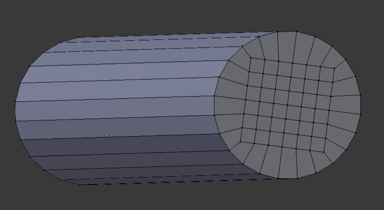
Below is shown the demo1 object as it looks when loaded into Blender. It consists of a mesh prism, constructed by hand from grid and circle.
Here is an application that makes it possible to assemble a hexahedral 3D mesh in Blender, then turn it into a real finite element mesh for use in IA-FEMesh, Elmer, Calculix, or others. This is possible because Blender is tolerant of non-manifold meshes, and because its .ply export script respects quadrilaterals. Like other apps dealing with 3D matter, Blenbridge appreciates clean input:
• no overlapping faces
• no errant vertices
• no unincorporated edges
In medium to large mesh models, the conversion time required can be a problem.
What follows is a loose description to familiarize the reader. The apps included in the basic tool chain include Blender 2.79b, Paraview 4.0.1, Gmsh 2.16, and IA-FEMesh 1.0. Blenbridge was written, compiled, and built in Lazarus 1.8.4 .
Demo 1
Below is shown the demo1 object as it looks when loaded into Blender. It consists of a mesh prism, constructed by hand from grid and circle.
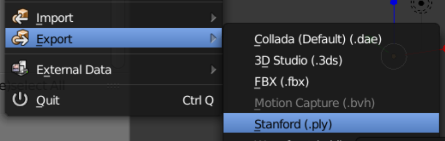
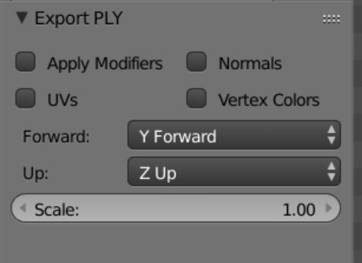
Right: the export menu in Blender. Stanford .ply is one of the standard export formats, and has the advantage that the numbering of the vertices matches the vtk system: both are zero-based.
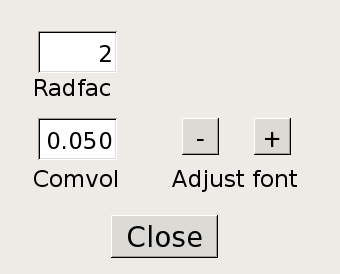
The options dialog for .ply export is shown on the right. All options are to be unchecked. The axis orientation is kept at default values so that the z-axis points up.
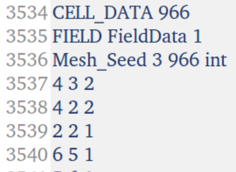
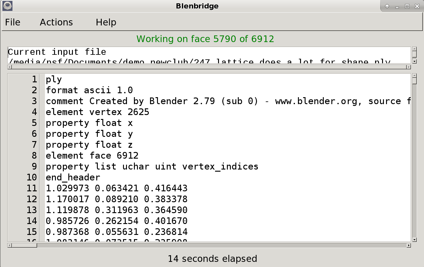
Above: a typical .ply file from Blender is loaded into Blenbridge and processed. The result file is given a .vtk extension and saved. The style of .vtk file produced is 'legacy unstructured grid', a useful type in the Vtk collection for describing finite element mesh.
As shown above, a dynamic label serves as a progress indicator. The ‘Conversion Complete’ message signals the end of the process. The appropriate conversion direction is set in the Action menu. The anticipated file extension is attached to the output file.
Note: The 'CELL DATA' block seen in the output file above is a Vtk field used by IA-FEMesh. Its presence does not bother either Paraview or Gmsh. However, if it is desired to import the .vtk file into Febio Preview, the Cell Data block must be removed first. (If the ‘Field Data’ submenu item remains unchecked, Blenbridge will finish slightly sooner.)
The conversion process consists basically of two steps: first, run Blenbridge on the desired file until no error messages appear, and second, open the resulting .vtk in Paraview until all the connected geometry is present.
About ‘Radfac’. Blenbridge attempts to build a hexahedral element from each face in the model. To do this, it sequentially looks at small subsets consisting of possible connecting faces. The variable Radfac, or ‘radial factor’, determines the size of the working subset of faces, and is multiplied times the separation distance between centroids of candidate faces to decide whether to include them in the current search. The default Radfac value is 2, and is effective on well-proportioned geometry, (and on some not so well-proportioned). For example, the long prism elements of the mesh depicted below, converted by a Radfac of 2, are all present. If an element or group of elements is not converted by Blenbridge, we may decide to increase the Radfac level and try again. However, it should be noted that in the majority of cases, it is the presence of a geometric defect, or multiple ones, which cause the conversion of a mesh to be incomplete.
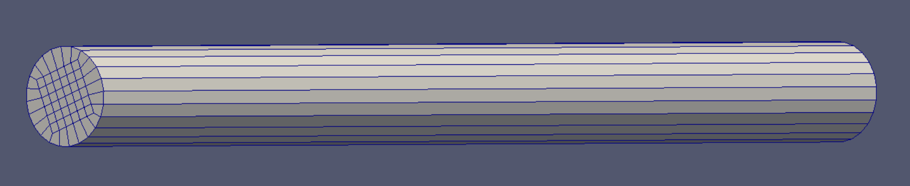
The .vtk output from demo1 is shown in Paraview. Paraview acknowledges the volumetric nature of the object, by using and saving volumetric connectivity, for example.
Demo 2
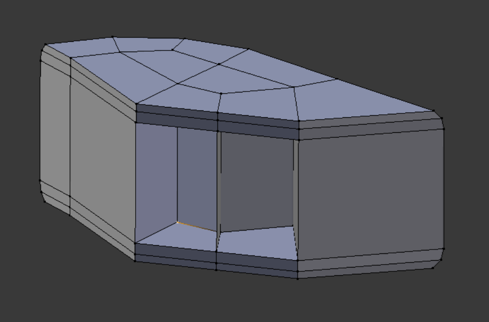
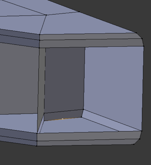
To the right is a pod corner object, shown in Blender. It has a couple of small defects.
To the right is a pod corner object, shown in Blender. It has a couple of small defects.
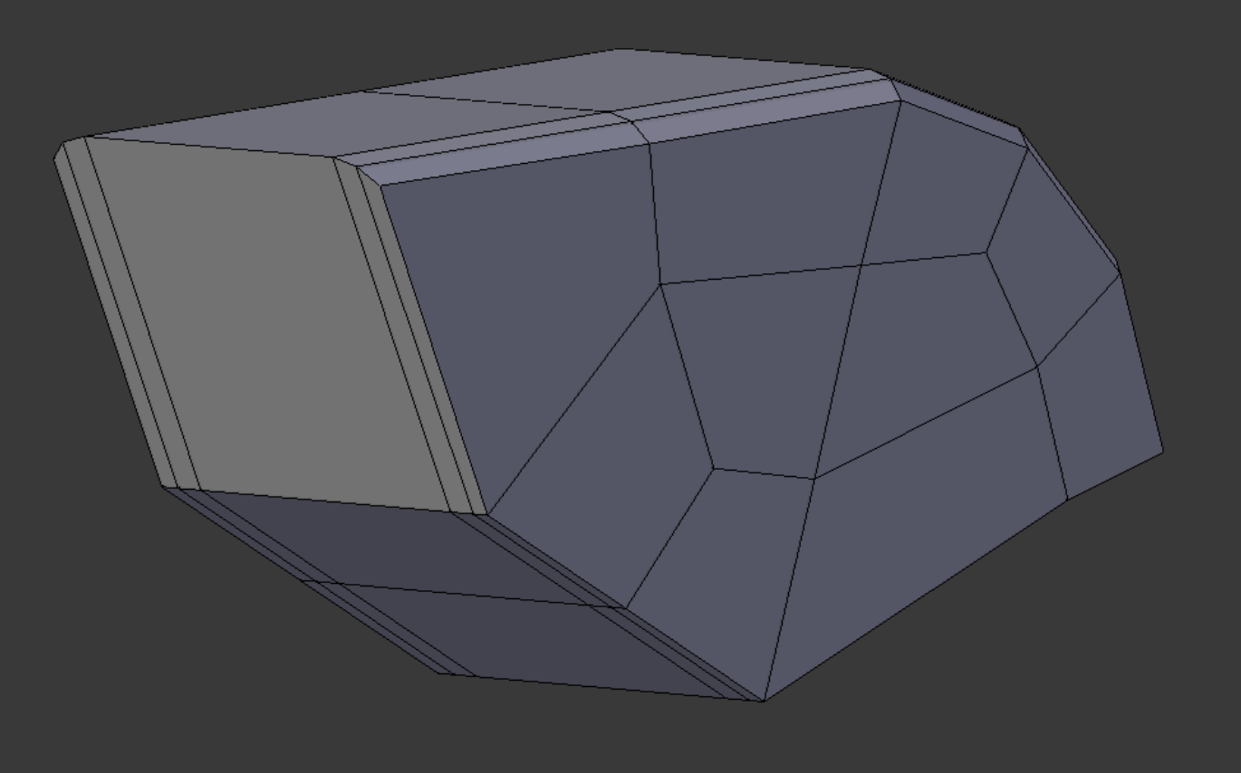
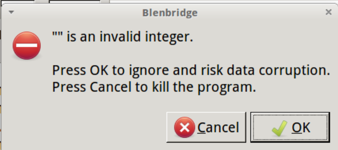
The error msg shown right meets us when we attempt to convert the .ply file into a .vtk in Blenbridge. The ‘invalid integer’ consists in a null character the program encounters when it reaches the end of a text line. In other words, an unexpected triangle. It is very helpful that most defects are interpreted as triangles by Blender’s .ply conversion script.
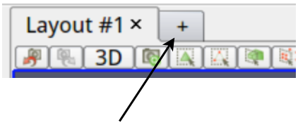
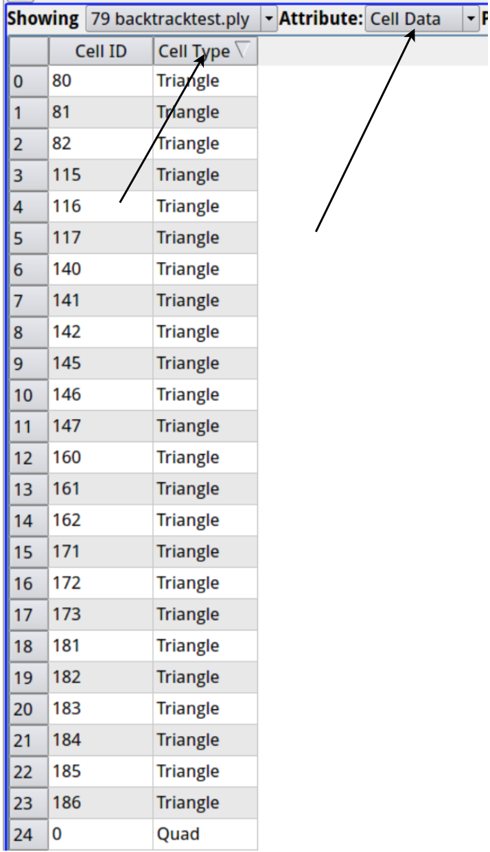
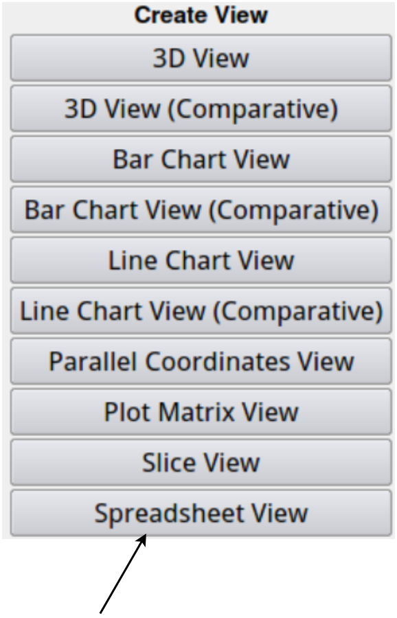
In Paraview, after the .ply file is opened, we open a new Layout, a Spreadsheet View. Toggling the Cell Type column, we see that the triangles are clearly listed. We select them, then apply the ExtractSelection filter to capture them.
(Notable fields in Paraview are arrowed.)
In Paraview, after the .ply file is opened, we open a new Layout, a Spreadsheet View. Toggling the Cell Type column, we see that the triangles are clearly listed. We select them, then apply the ExtractSelection filter to capture them.
(Notable fields in Paraview are arrowed.)
By showing both the main representation and the ExtractSelection at the same time, and reducing the opacity of the former, we can see where the triangles are.
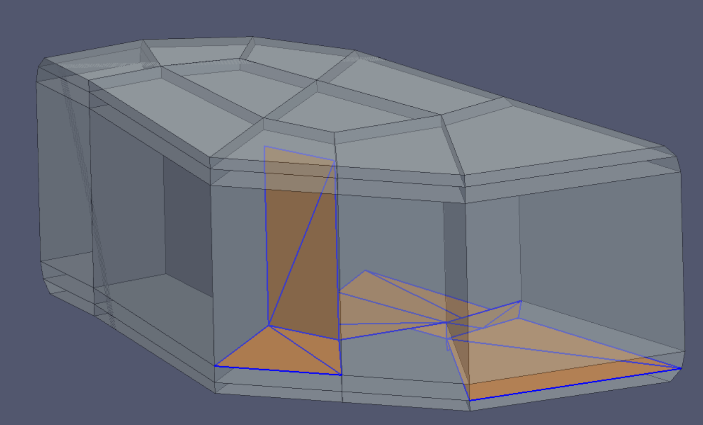
Two defects are easily hunted down (and shown selected at right): An extra vertex close to a corner, just out of reach of Blender’s RemoveDoubles command. And another vertex in the middle of an edge where RemoveDoubles would not reach it. After these problems are corrected, we can convert the file without further difficulty.
Demo 3
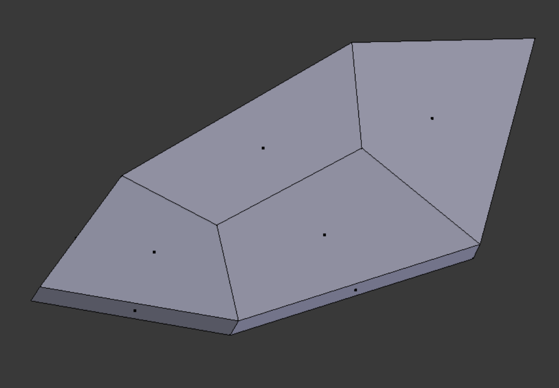
Here is a small segment of a larger curved surface. Its lack of flatness can make a problem for Blenbridge, which the variable Comvol deals with.
Here is a small segment of a larger curved surface. Its lack of flatness can make a problem for Blenbridge, which the variable Comvol deals with.
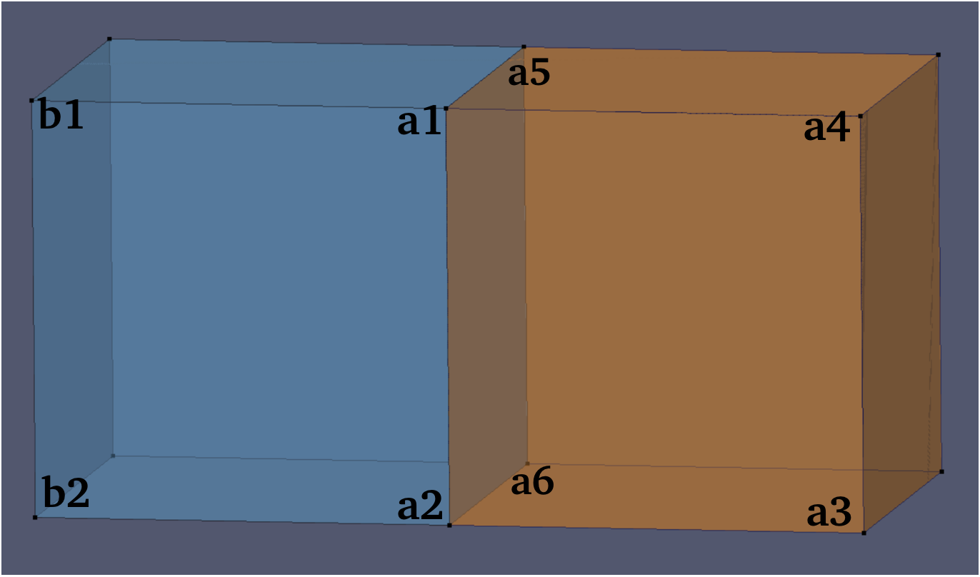
Referring to the two cube shapes shown below, suppose we are attempting to create an element from the six orange faces, starting with the front face and concentrating on the edge a1-a2. This edge is shared by the face a1-a2-a6-a5 and by the face b1-b2-a2-a1. Operating blind, Blenbridge would see no particular difference between the attached faces, and might choose the wrong one. But consider the tets a1-a2-a4-a5 and b1-a1-a2-a4. The first has a significant volume, but the second does not. Therefore if the volumes of a tetrahedron containing a prospective face’s points (plus base face points) is compared with a characteristic bounding volume, or a proxy of it, the correct components can be chosen. This ‘comparative volume’ attribute is governed by the value of Comvol.
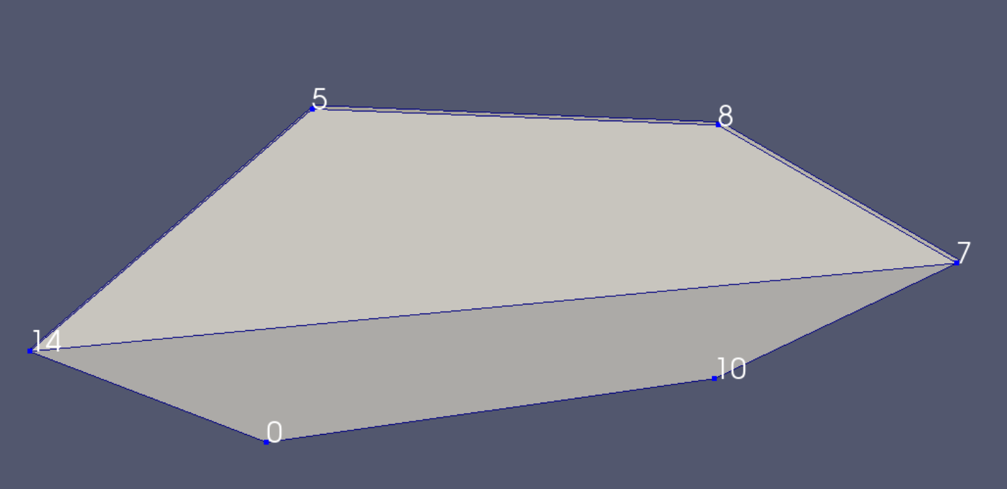
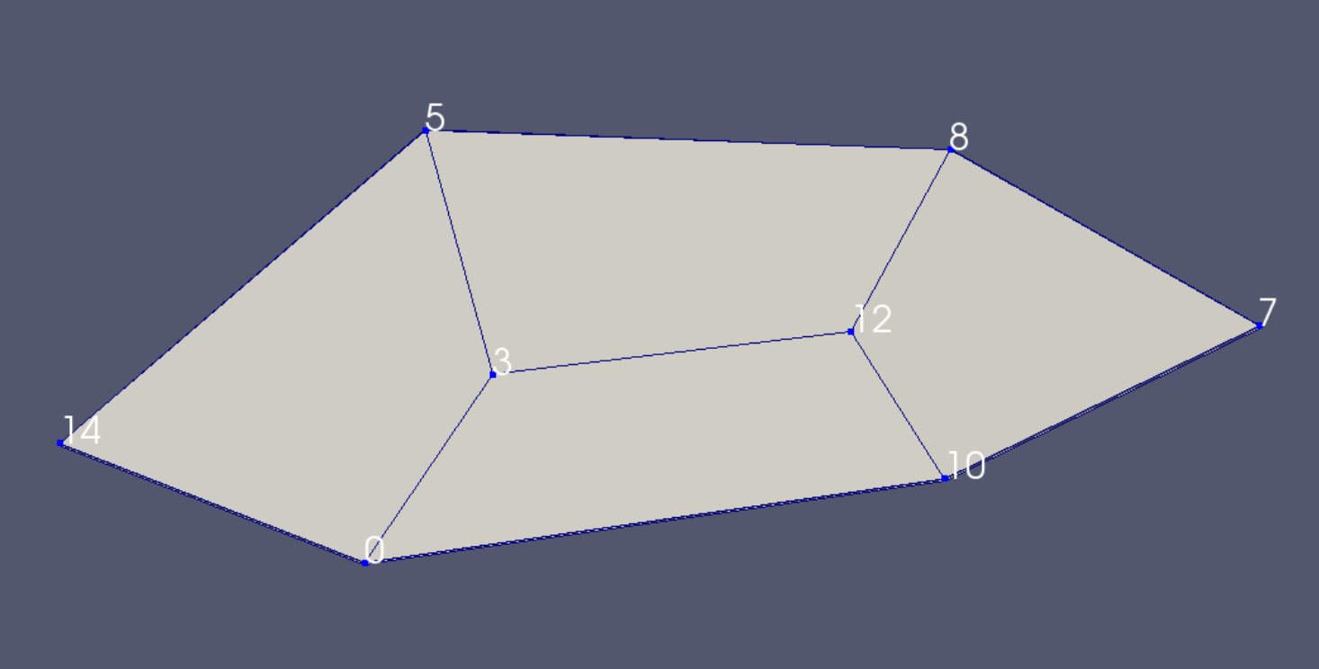
If a Comvol value of less than 0.016 is used, the erroneous conversion shown right, above, is produced. If a Comvol value of 0.016 or greater is used, the correctly depicted mesh conversion shown right, below, is produced. The default value of 0.050 for Comvol is satisfactory for all the demos in this document except one. For a case where an exception causes a different value of Comvol to be used, see
p. 73
.

If text overlaps pictures, it means that font size needs to be reduced. After such font size reduction, the user may wish to boost the page's zoom.