Demo 11
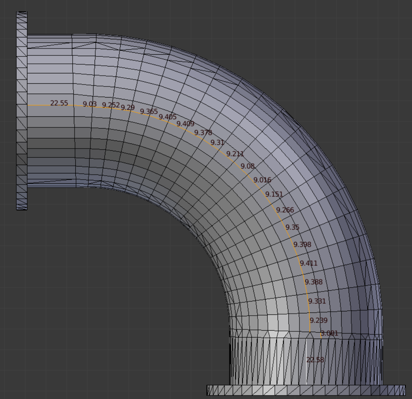
This object is a 90-Degree Ell; the model is held at the INRIA model repository as an .obj file, and is imported into Blender with Blender ’ s .obj import script. Its title is “Y7034” (See References). We apply the mesh command Tris to Quads and then Limited Dissolve at a level of 5 degrees. A predominantly quad structure remains, but it is somewhat irregular, and internally a large number of faces would need to be created to attain enclosed elements throughout. We elect to rebuild the model. The picture at right shows the edge lengths revealed in Blender.
This object is a 90-Degree Ell; the model is held at the INRIA model repository as an .obj file, and is imported into Blender with Blender ’ s .obj import script. Its title is “Y7034” (See References). We apply the mesh command Tris to Quads and then Limited Dissolve at a level of 5 degrees. A predominantly quad structure remains, but it is somewhat irregular, and internally a large number of faces would need to be created to attain enclosed elements throughout. We elect to rebuild the model. The picture at right shows the edge lengths revealed in Blender.
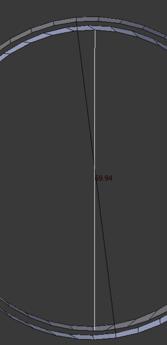
The Outer and Inner diameter of the original model are measured as shown.
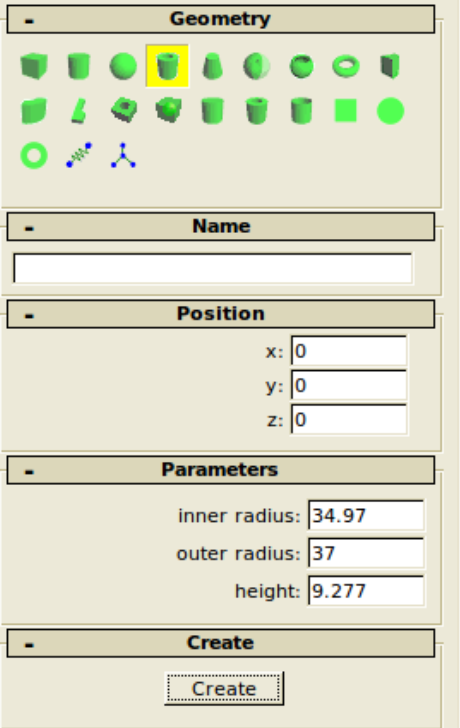
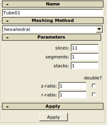
The Febio Preview dialog boxes are shown which produce one single segment of pipe mesh. After it is created, Blenbridge converts it to .ply format, which Blender imports. Of course we could have just as easily have created the pipe segment by extruding circles inside Blender.
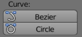
In Blender’s Object mode, the single pipe segment is partnered with a bezier circle, created from the toolbox panel.
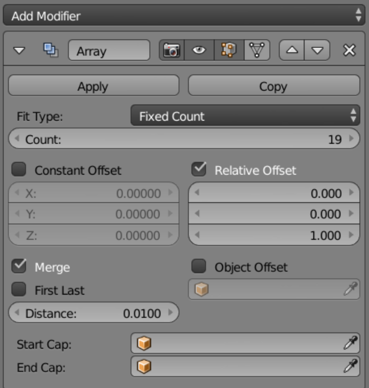
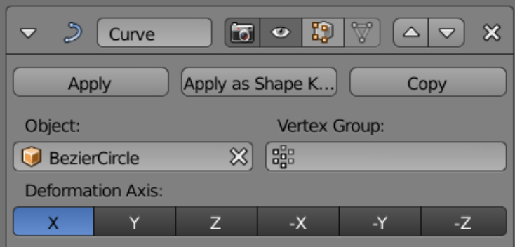
The array modifier is added to the segment, then a curve modifier is added on top of that.
When the created geometry meets all requirements, the two Apply buttons are pressed, and the bezier circle is no longer needed.
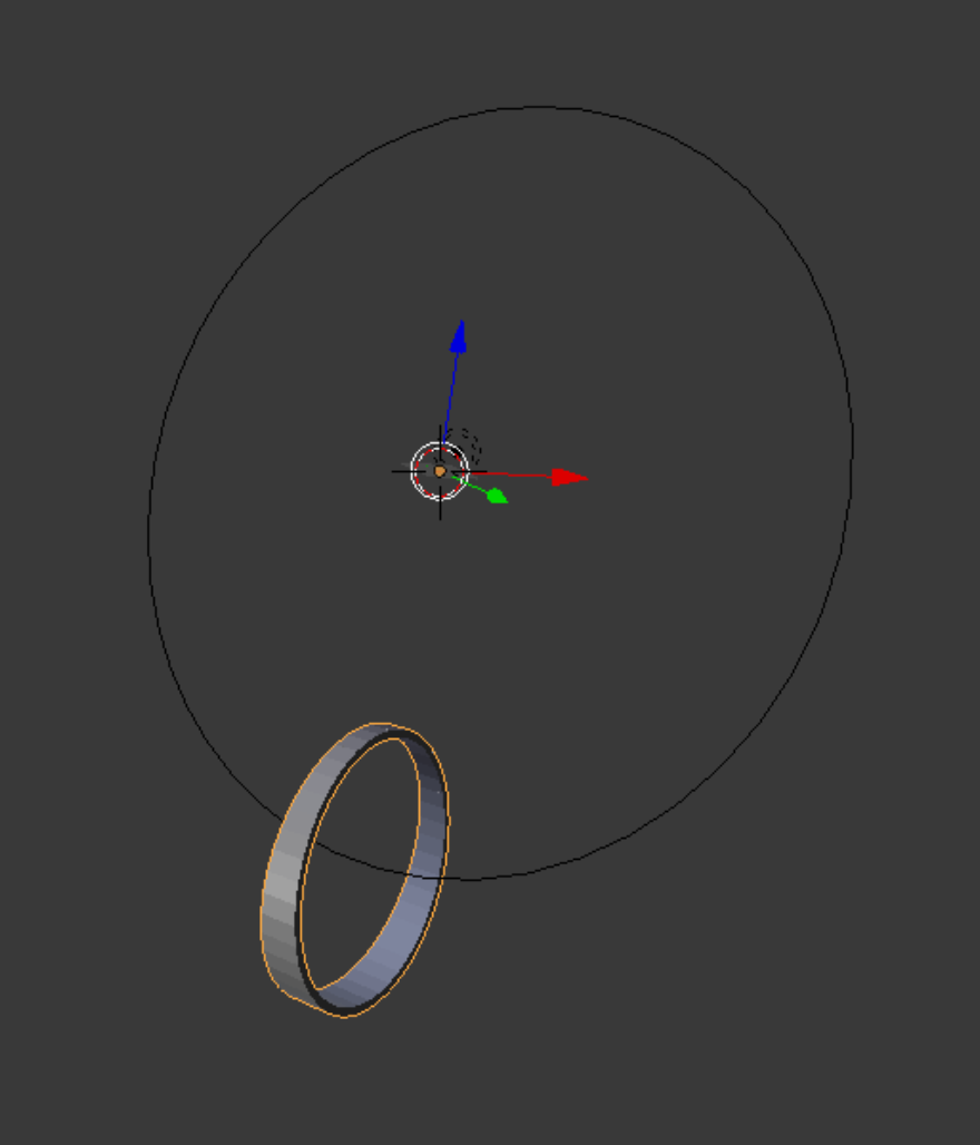
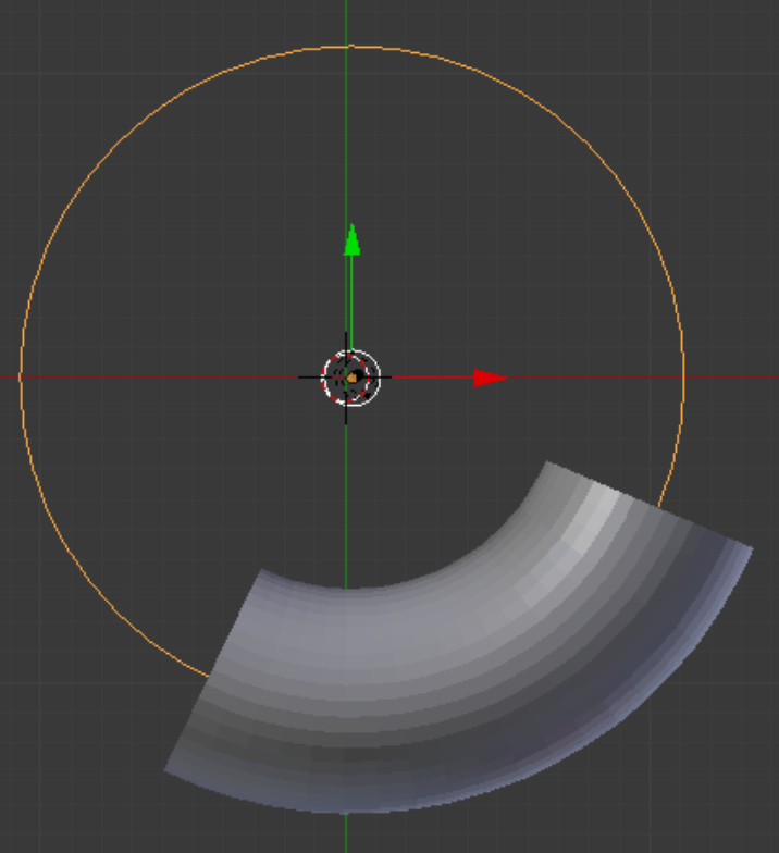
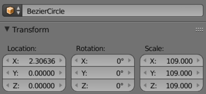
With all 19 pipe segments conforming to the bezier circle, the view looks as shown right. Note that if the bezier circle is edited in Edit mode, the curves of the group of pipe segments change. Theoretically, based on total length, the bezier circle should have a diameter of 112.2; however, the best fit was with a circle diameter of 109.
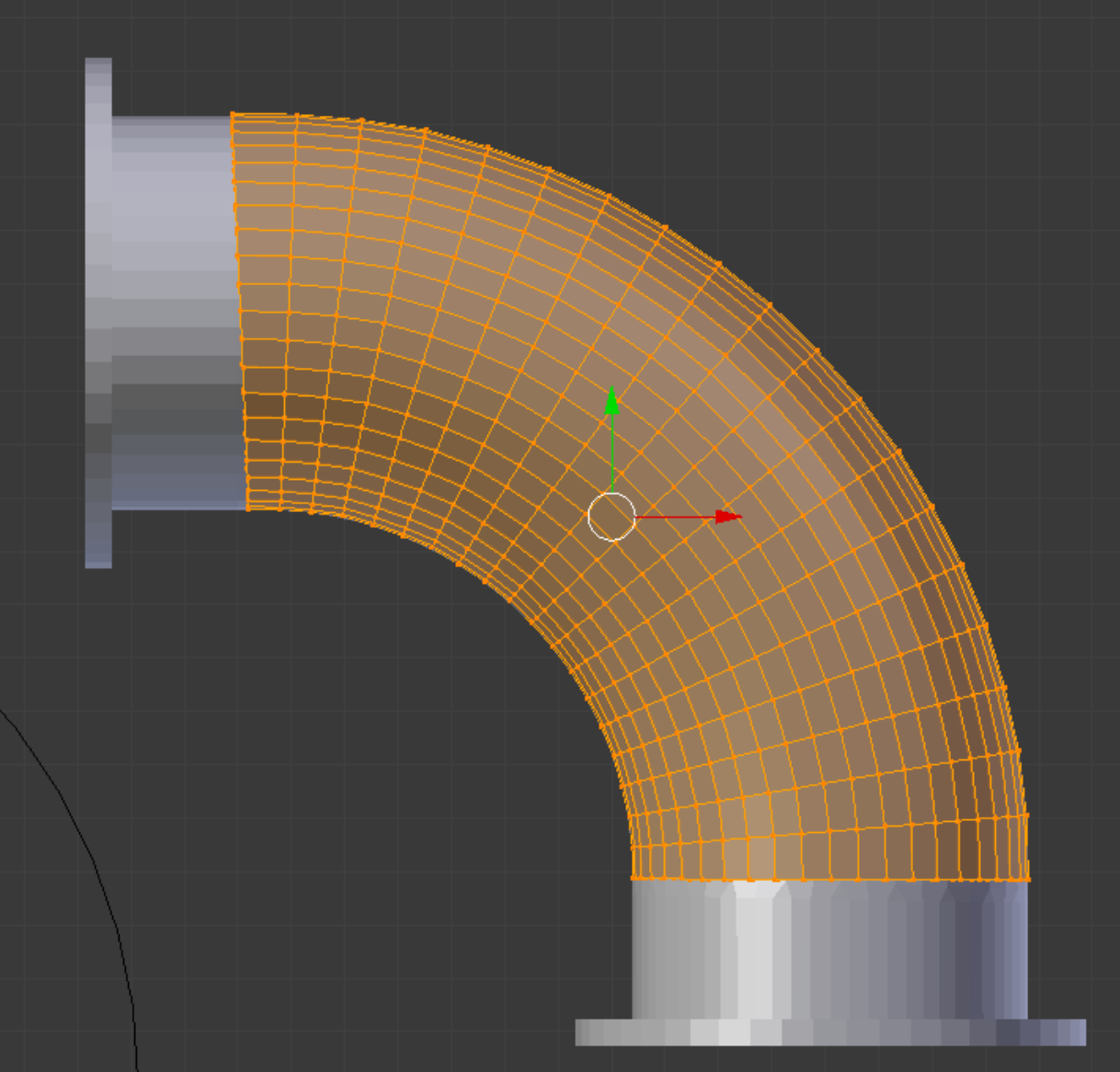
In orthographic perspective, the group of pipe segments is shown in front of the original model, which we have appended for the comparison.
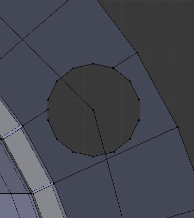
When Blender adds a circle, it holds the requested number of vertices and the radius in memory and presents these values the next time it is called on to add a circle. This makes Knife Project easier. Circles are added, used as cutters, and then destroyed repetitiously, and the ‘drilling’ of the 12 holes in the flange is quickly done. The template hole circle itself (only one of twelve center points is shown at right) was constructed from the original flange holes. There we established the centers of two opposite holes by bisection, and then drew a temporary edge between, which showed the numerical distance.
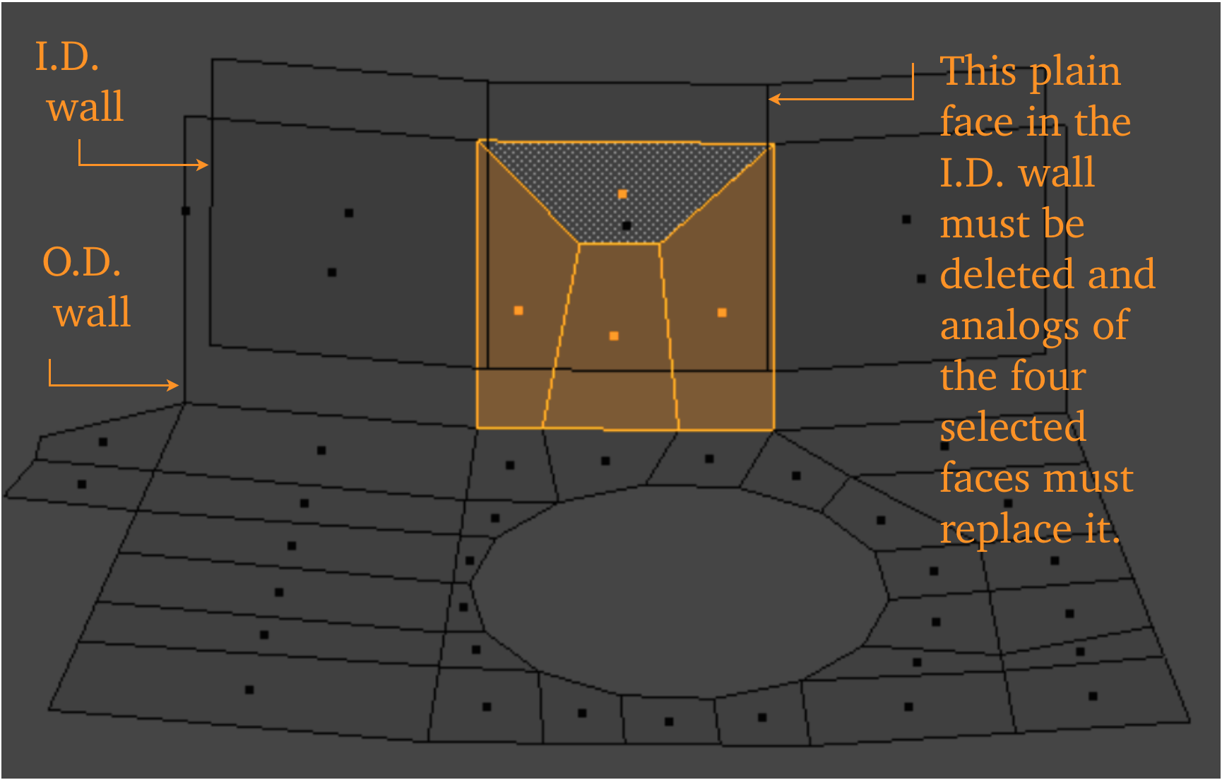
After the flange holes have been installed, we must add edge relief to some of the hole segments. At right are shown the relief faces that need to be transferred to the I.D. wall as duplicated faces. This transfer can be accomplished in any way that produces elements of an analogous shape while keeping the quality of newly created elements at a satisfactory level.
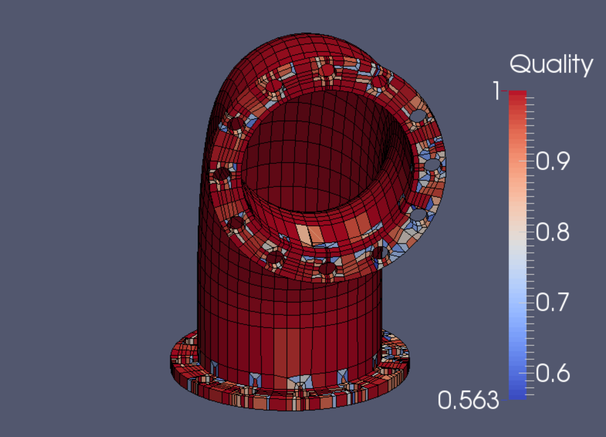
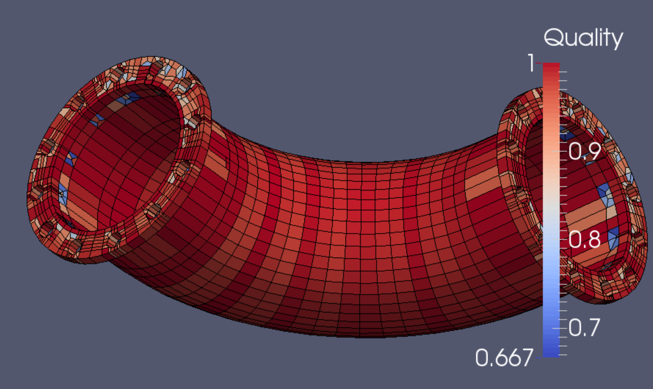
At right is shown the quality filter result for Scaled Jacobian; below is that for Diagonal measure. Both are in the satisfactory range.
At this level of refinement, it has 2011 elements and 4537 nodes.
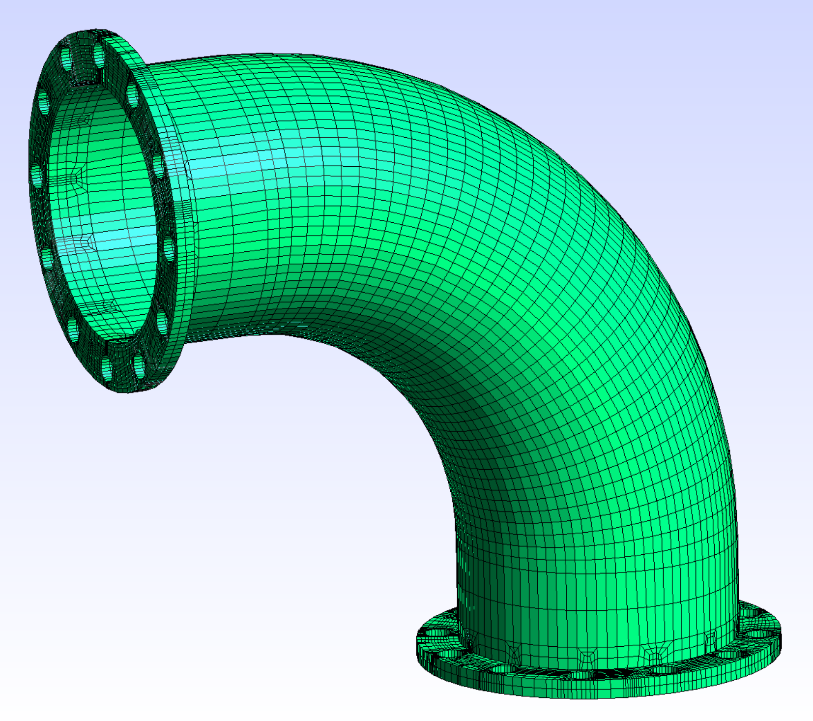
After one refining subdivision in Gmsh, the mesh would have 16,088 elements and 25,748 nodes.