Demo 16
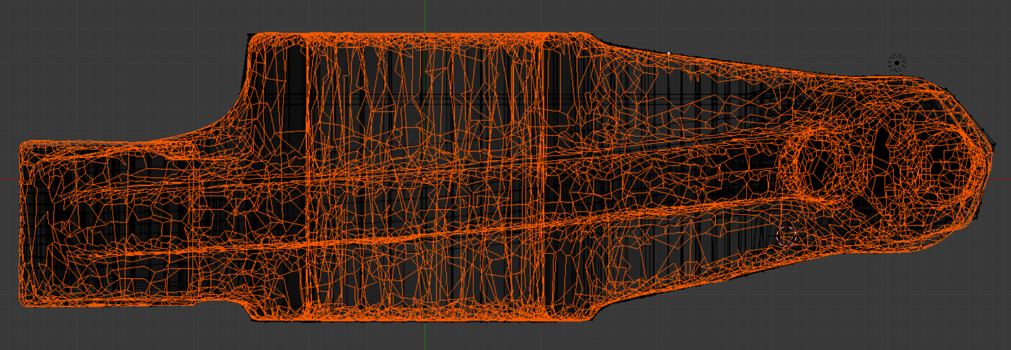
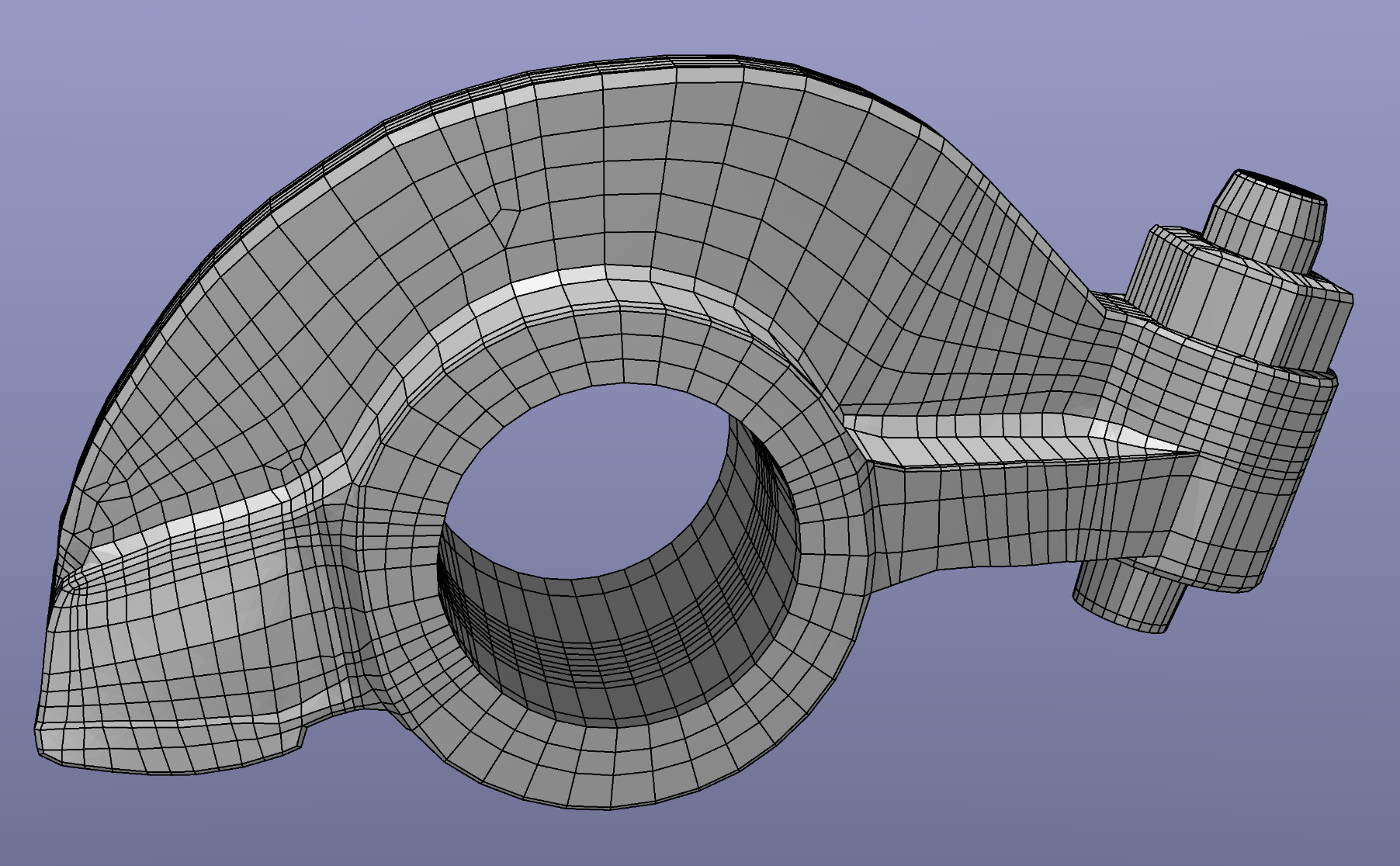
This object is a rocker arm; the model can be found in the INRIA model repository as a .ply file, and is imported into Blender with Blender ’ s .ply import script. Its title is “rockerarm 25” (See References). It is evidently the product of an optical scanning process. The usual Tris-to-Quads and Partial Dissolve commands are given, the latter with a Max Angle of 20 degrees.
This object is a rocker arm; the model can be found in the INRIA model repository as a .ply file, and is imported into Blender with Blender ’ s .ply import script. Its title is “rockerarm 25” (See References). It is evidently the product of an optical scanning process. The usual Tris-to-Quads and Partial Dissolve commands are given, the latter with a Max Angle of 20 degrees.
We proceed to introduce a geometrical framework for the mesh. We notice some peculiarities relating to actual samples of machine work performed on castings. For example, the bore and its lip are not concentric.
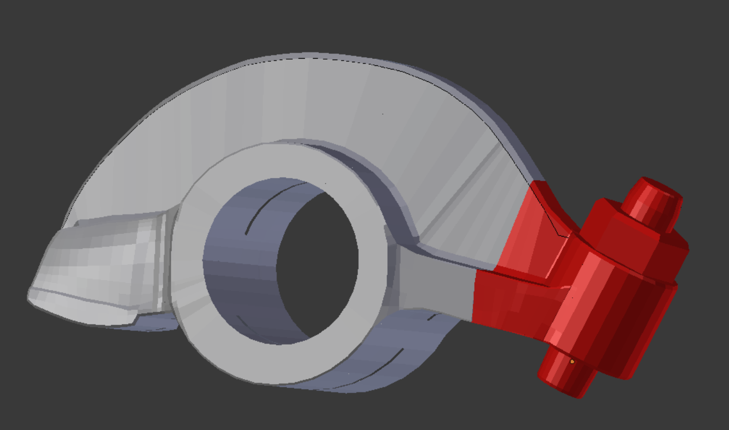
With an appropriate template, we can execute the locknut assembly as a continuous sequence of extrusions.
An extruded outline of the rocker/bore/wing section gives us a place to start. An early version of the locknut assembly is positioned to give a rough preview.
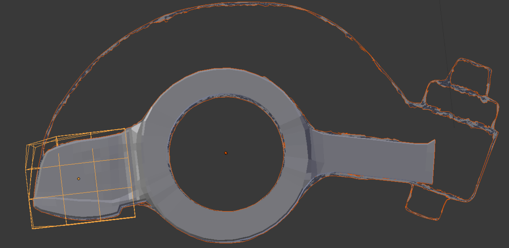
One Blender tool that works with non-manifold meshes is the Lattice modifier. Here it is the last of three objects selected in Object mode. Then the lattice is edited in Edit mode to fine tune the shape of the rocker.
We break off a chunk of wing tip as a separate object and cut it in way of the locknut assembly. Edges from the locknut barrel are seen here out of cutting position. Whenever the Knife Project tool is made up of a series of connected edges, like the arc shape shown here, stray points are scattered along its path. Merging these with existing points after the cut can be a chore.
The locknut assembly is fitted to the wing and web. Paraview can be used to identify first triangles, then low quality elements, in the area of the join.
Top, side, and front orthographic views, superimposed on the workpiece, guide the phases of the construction. Too great a reliance on this simplistic method can cause deficiencies in the resulting mesh.
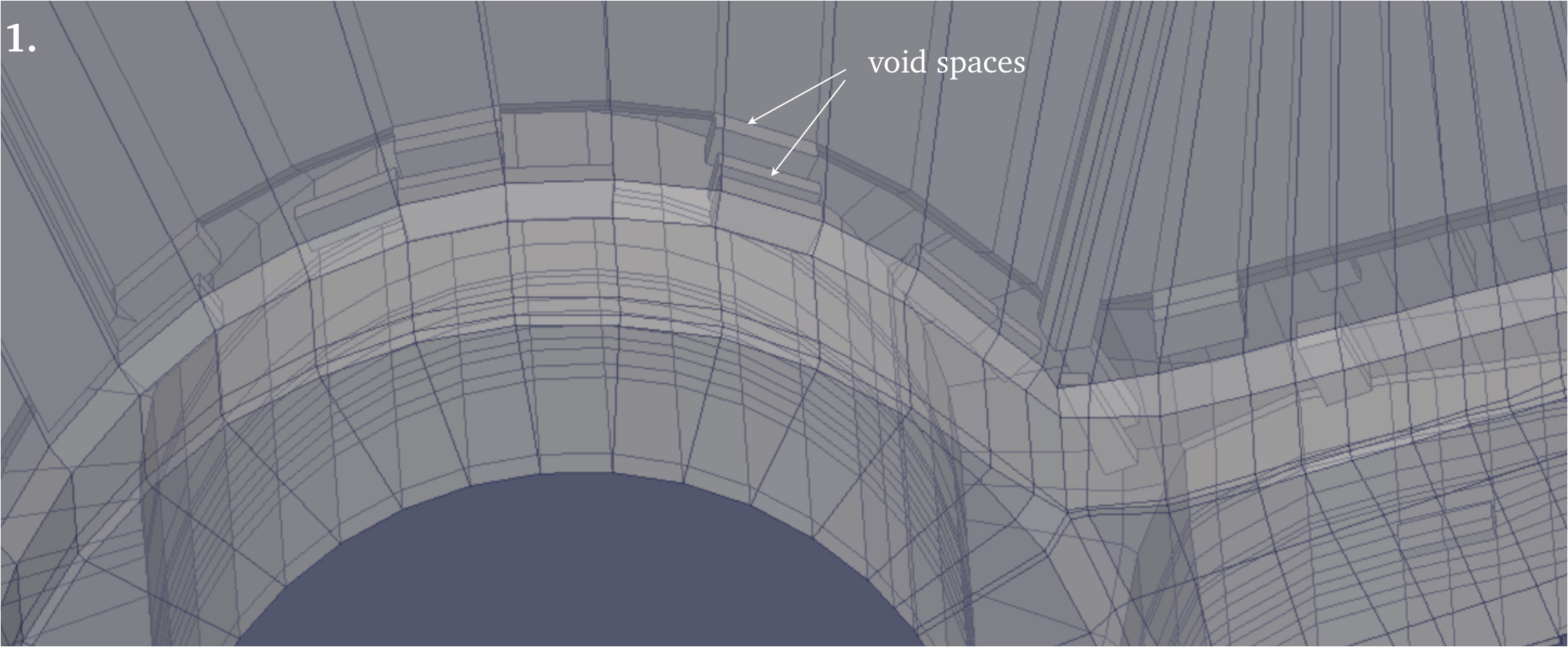
1. By reducing the opacity in the presentation view of the .vtk model in Paraview, we can see inside and identify void spaces, where elements are incomplete.
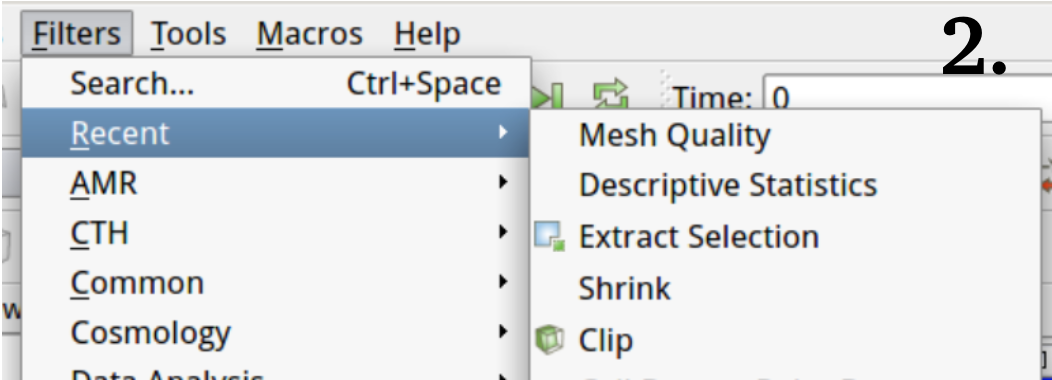
2. The Filters menu, showing five filters we especially rely on.
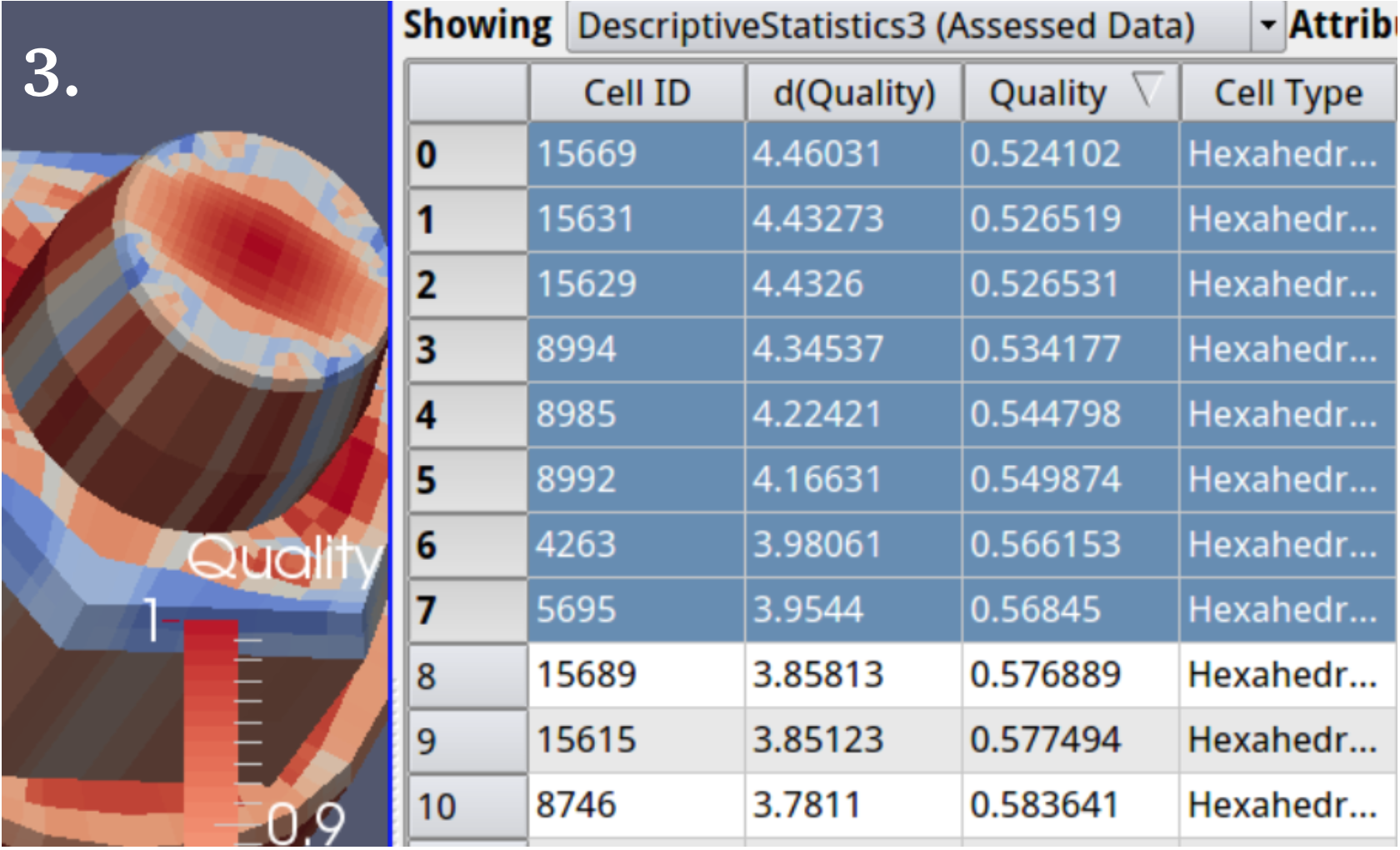
3. A common task sequence is to put a Descriptive Statistics filter on top of a Mesh Quality filter, then sort by quality and highlight, automatically making a selection of the highlighted cells. Then an Extract Selection filter applied to the Descriptive Statistics filter grabs the selection as soon as applied.
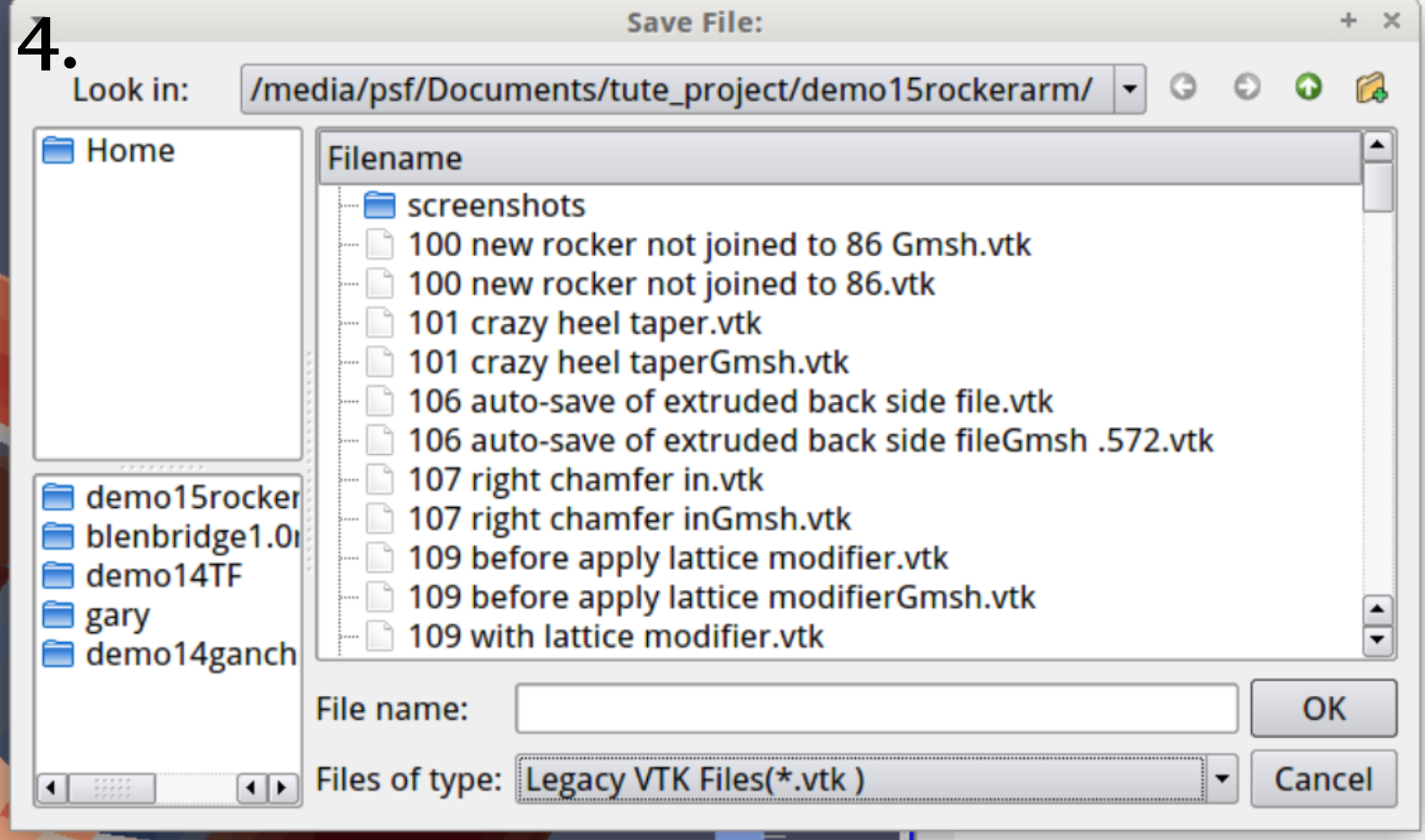
4. Continuing number 3., the Save Data menu option under the File menu allows the extracted selection to be saved as a legacy .vtk file, which Blenbridge can convert to a Blender-readable .ply file. As an object in Blender, the group of elements stand on top of their Blender
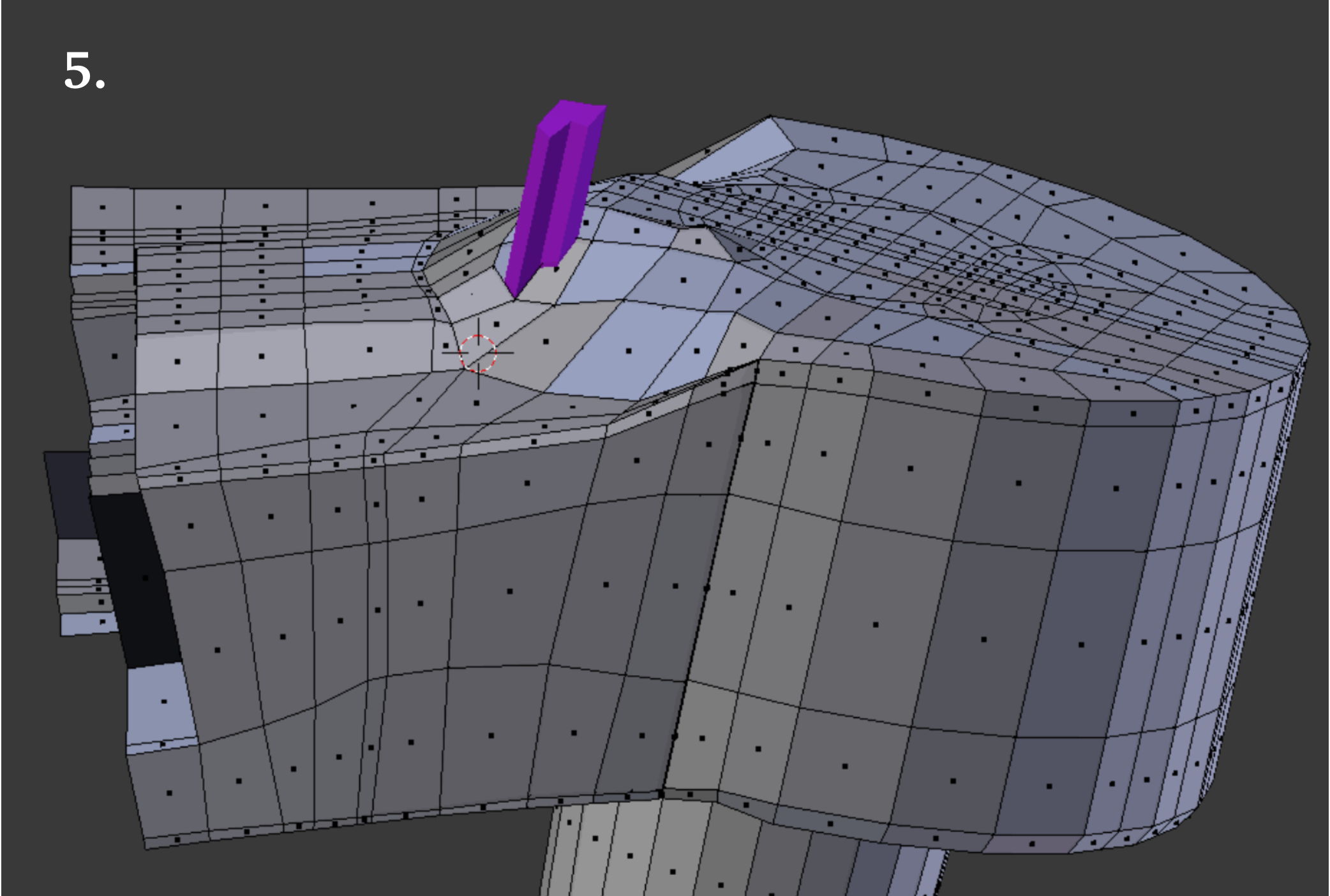
counterparts, for perfect identification. 5. The element group described in 4. is non-selectable in Edit mode.
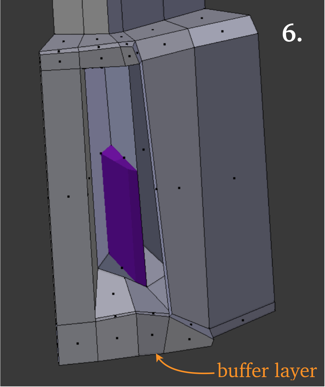
6. Breaking off a chunk for free editing as a separate object and then re-joining is convenient, but it is important to include a buffer layer whose outer boundary will not be altered.
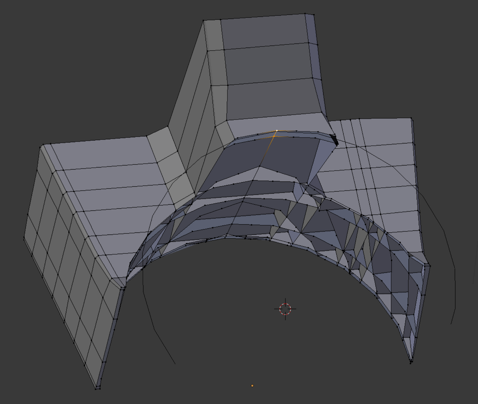
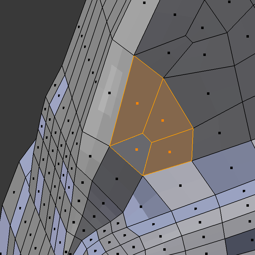
The group of four faces and underlying elements shown selected at right is not converted correctly with the default Convol value of 0.05. An odd thin element with extremely low quality is produced in this case by Blenbridge, and it is necessary to increase the Comvol value to the unusually high value of 0.25 before the expected elements are created.
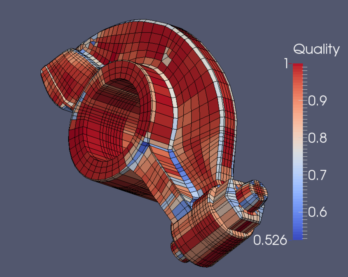
The Verdict mesh quality appraisal is satisfactory for both Scaled Jacobian (above) as well as for Diagonal measure (left).
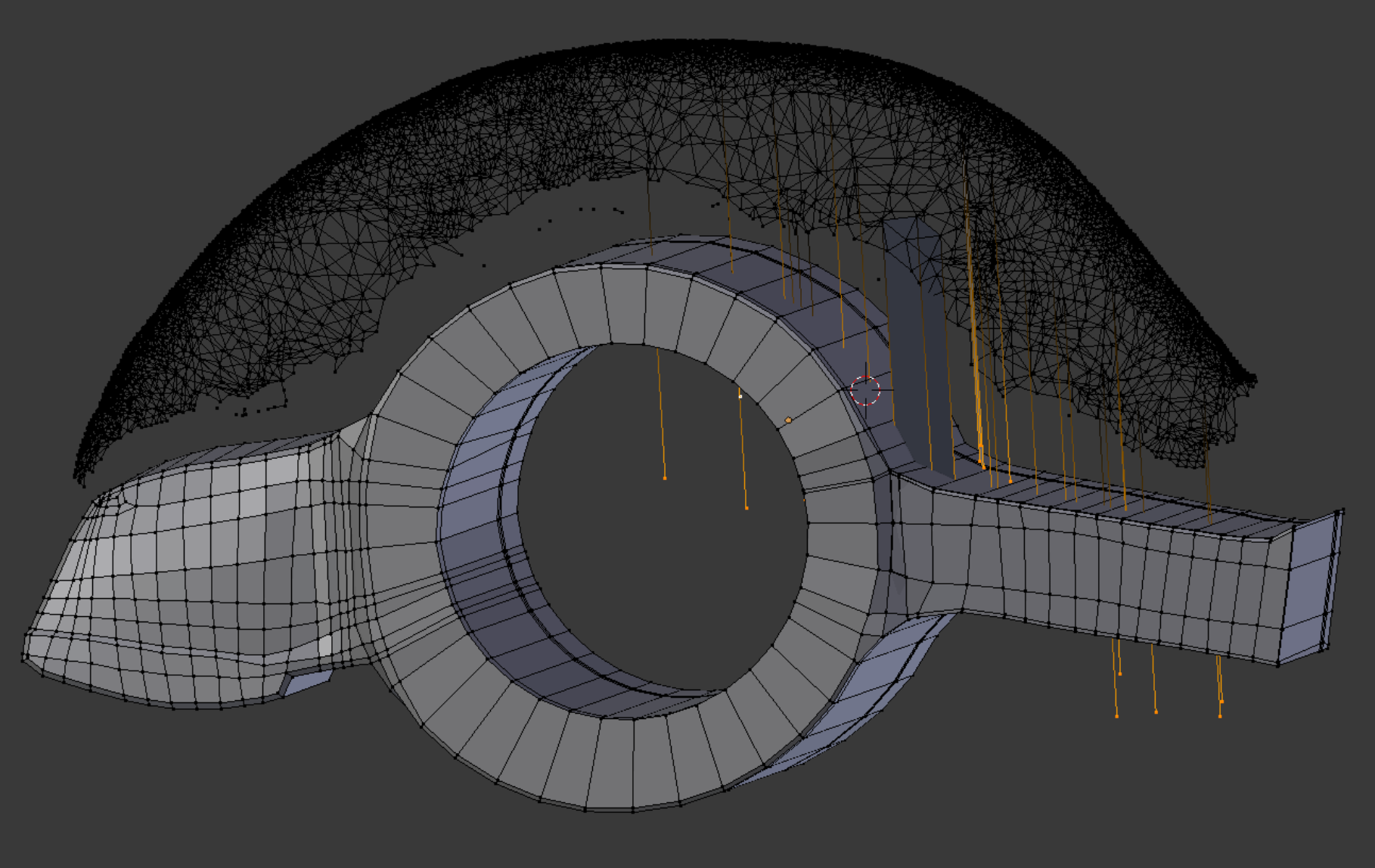
The web is not aligned with a major global axis. Its central plane is also slightly curved. Here we drop points along the z-axis to locate the web’s base position on the rocker arm surface.
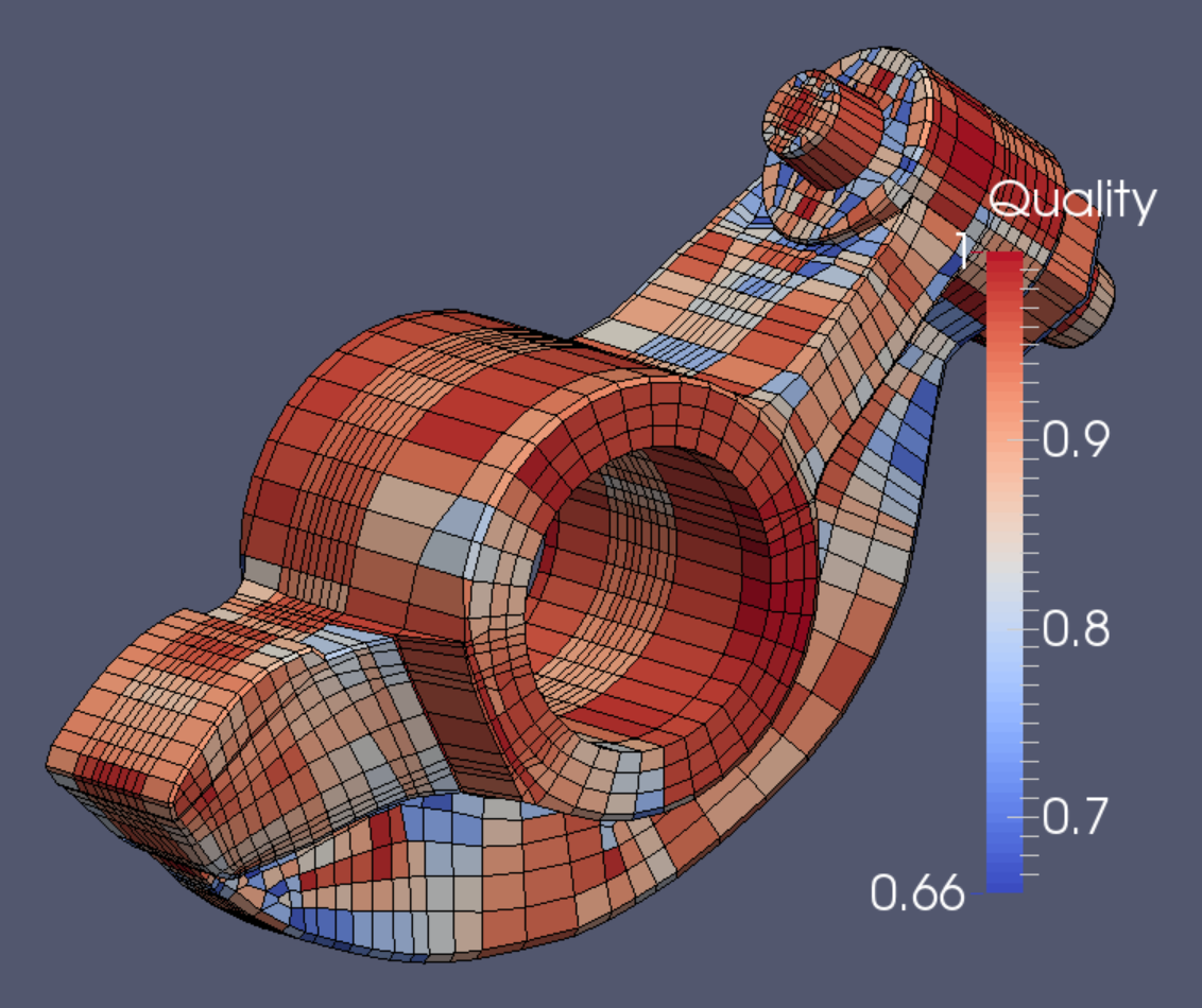
The final mesh contains 9240 elements and 11,322 nodes.